Planning the cable path
OmniTrax Product Guide Page 51
Sensor cable bypasses (hardware bypass)
Use a spliced-in sensor cable bypass:
• where obstacles (e.g., buildings, streams or ponds, driveway, roadway, walkway, sallyport,
culvert, tree, large rocks, etc.) block the sensor cable route away from a processor or
decoupler/terminator location
• where an area of non-detection, which does not meet the criteria for a software bypass, is
desired (e.g., a gate, or roadway)
• to cross a metal fence boundary, which cannot be replaced by a non-metal panel
Lead-in cable splices
A cable splice is used to:
• to increase the 20 m (65 ft.) length of the lead-in (non-detecting) cable
• replace a damaged section of cable with new cable (see Repairing sensor cables
on page
154)
• to create an area of non-detection within an active cable set
Adding lead-in cable (OC2)
You can add 10 m or less of OC2 lead-in cable, without making any other changes. In this case,
you use the 20 m of integral lead-in cable plus up to 10 m of additional non-detecting cable to
augment the lead-in cable (max. length of lead-in cable = 30 m). You also require an OC2 cable
splice kit.
To add more than 10 m of OC2 lead-in cable, you must remove an equal length of detecting cable
from the beginning of the detecting cable (marked by the red band). You will require an OC2
cable splice kit and the full length of lead-in cable required (two pieces, RX and TX). For example,
if site conditions require 75 m of lead-in cable, you must cut out 55 m of detecting cable, measured
from the red band. You then splice in a 75 m section of lead-in cable to replace the 55 m of
detecting cable and the 20 m of integral lead-in cable that was cut out. You should label and retain
the cut out section of lead-in and detecting cable for future repairs.
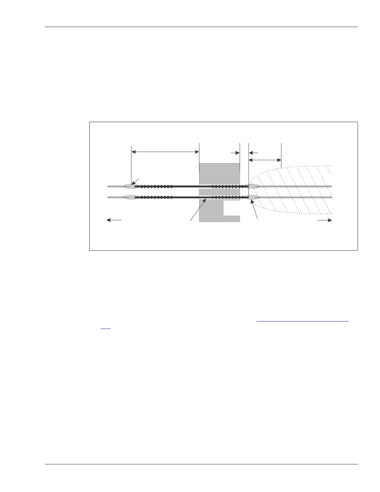
Figure 24: Sensor cable hardware bypass
7 m (23 ft.)
ferrite
bypass start point
(cable splice)
required section of non-detecting cable = 7 m + width of obstacle + 30 cm
required section of detecting cable removed = 7 m + width of obstacle + 30 cm
required software bypass = 7 m + width of obstacle + 30 cm + 4 m
30 cm
(12 in.)
4 m (13 ft.)
detection field requires 4 m
(13 ft.) to build up to full strength
detecting cable
non-detecting cable
conduit
through obstacle
NOTE: The OC2 cable in this figure uses 2 Male TNCs and a Female coupler at each splice point. SC1
and SC2 splices are joined with Male and Female TNC connectors.
obstacle
beads
bypass end point
(cable splice)
to
decouplers
to
processor