Relay output alarm communication
OmniTrax Product Guide Page 175
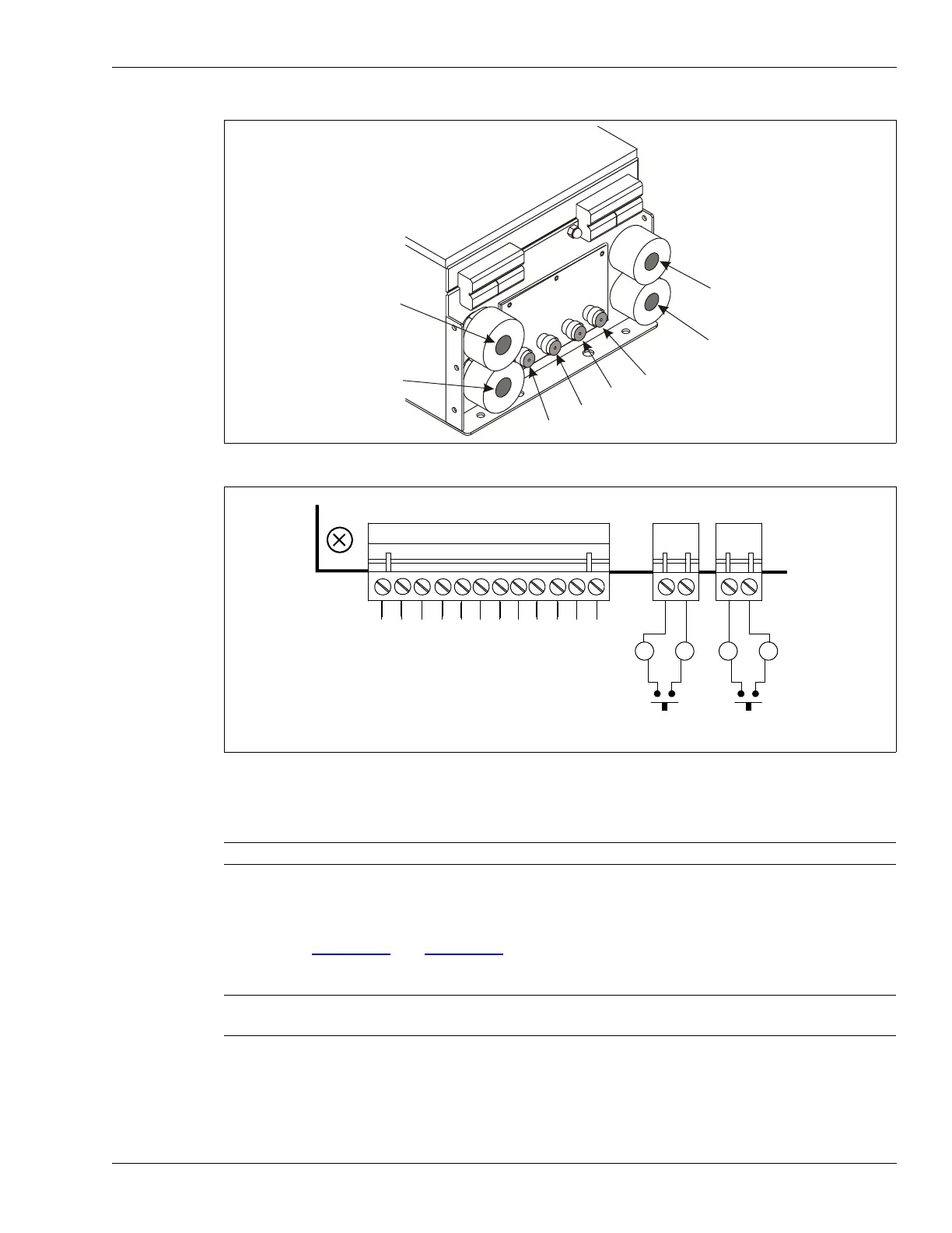
Connection procedure
1. Connect the lead-in cables to the bulkhead TNC connectors in this order (from left to right)
TXA, RXA, RXB, TXB.
2. Pull the I/O wiring into the enclosure.
3. Pull the power cable (if required) and ground wire into the enclosure.
4. Refer to Figure 151:
and Figure 153: to make the
I/O wiring connections.
Figure 152: Sensor cable connections
Figure 153: Local control mode input/output wiring
Note Remove the cable glands to pull the I/O wiring into the enclosure.
Note Senstar recommends the use of data link lightning arrestors at any point
where copper wires enter or exit a building.
bottom of enclosure
earth ground cable gland
I/O wiring cable gland
sensor cable bulkhead connectors
power input cable gland
I/O wiring cable gland
self test inputs
(momentary switch input, NO contacts, unsupervised)
AUX 2
AUX 1
K
1
F
A
I
L
N
C
K
1
F
A
I
L
C
O
M
K
1
F
A
I
L
N
O
K
2
S
U
P
N
C
K
2
S
U
P
C
O
M
K
2
S
U
P
N
O
K
3
A
L
M
A
N
C
K
3
A
L
M
A
C
O
M
K
3
A
L
M
A
N
O
K
4
A
L
M
B
N
C
K
4
A
L
M
B
C
O
M
K
4
A
L
M
B
N
O
default relay
configuration: