Telecom enclosure wiring
Page 170 OmniTrax Product Guide
Connecting the telecom enclosure tamper switch
The telecom style enclosure includes a tamper switch and a wiring harness to connect the switch
to the OmniTrax processor. The wiring harness enables a series connection so that the OmniTrax
weatherproof enclosure’s tamper switch also remains connected.
1. Open the OmniTrax enclosure and disconnect the tamper switch from T8 on the processor
circuit card.
2. Plug the OmniTrax enclosure’s tamper switch connector into the two pin locking header on the
supplied wiring harness.
3. Plug the other connector on the supplied wiring harness into T8, the two pin locking header, on
the processor.
4. Run the two leads on the wiring harness out of the OmniTrax enclosure through the right side
data cable port.
5. Press fit the tamper switch bracket onto the front edge of the telecom enclosure near the
bottom.
6. Splice the two wires from the telecom enclosure tamper switch to the two wires on the wiring
harness (polarity does not matter).
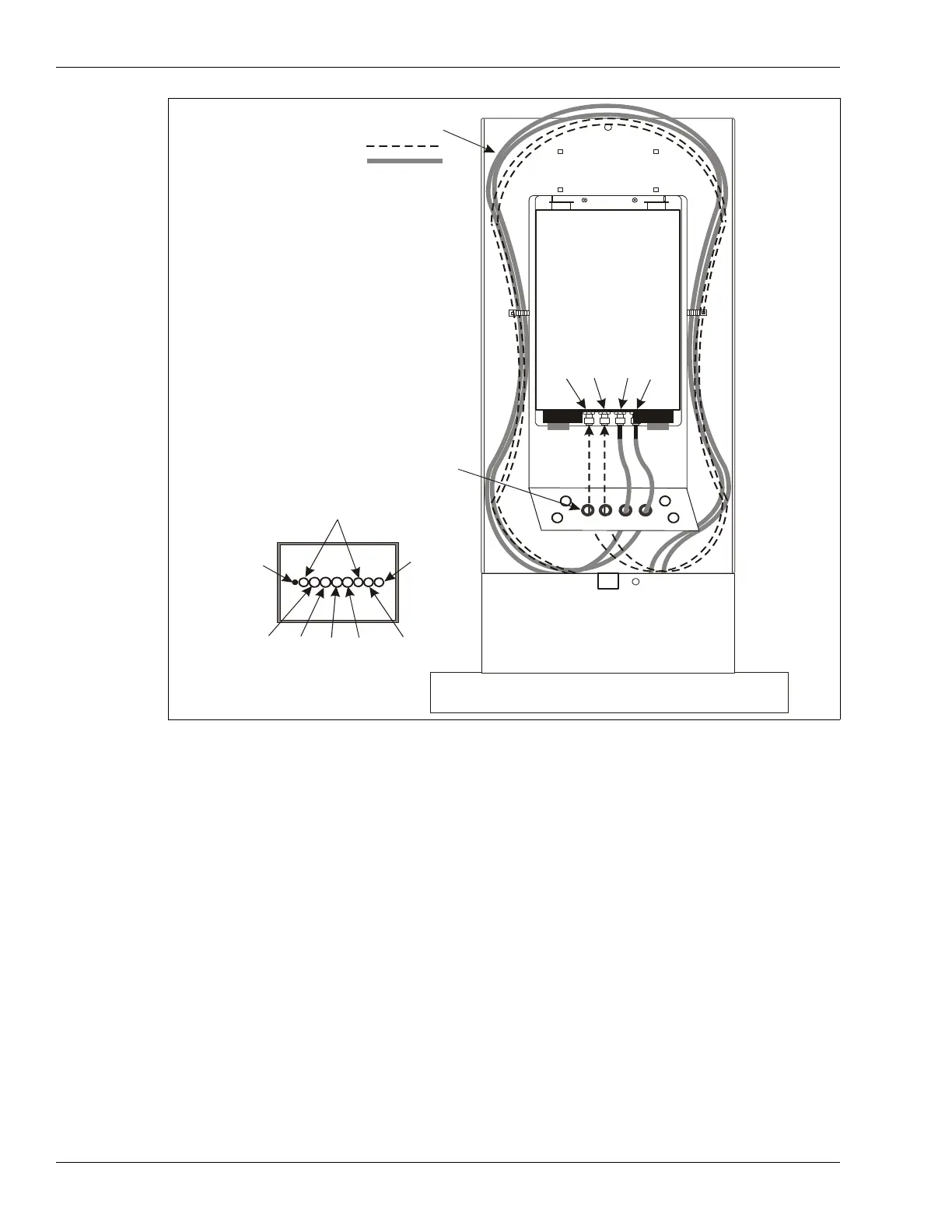
Figure 149: Routing OC2/SC2 sensor cables into the telecom enclosure
enclosure
telecom enclosure
concrete foundation
auxiliary sensor/data
cable conduit
earth
ground
drain
pipe
power cable
conduit
conduit layout
(in concrete foundation)
TXA
RXA
TXB
NOTE: Form a 2 m (6.5 ft.) service loop
by wrapping the cables once
around the inside of the telecom
enclosure.
Power cable, ground wire and
data cables not shown.
OmniTrax lead-in cables
TXA
RXA
RXB
TXB
install the 4 protective grommets