Cable tests
Page 150 OmniTrax Product Guide
Leakage resistance test (all cable pairs)
1. Select a sensor cable pair to test. Disconnect both connectors, allowing the connectors to
hang in mid-air during this test.
2. Set a digital multimeter to measure resistance, and attach it to the connector’s shell and the
processor ground rod.
• The resistance should be > 20 M
If the reading is different, there could be a problem with the sensor cable’s jacket or with
heatshrink installation.
3. Reverse the multimeter’s leads (connector’s shell and the processor ground rod) and repeat
the resistance measurement.
• The resistance should be > 20 M
If the resistance is different, there could be a problem with the connector installation.
4. Set the digital multimeter to measure Volts DC. Measure the voltage between the center pin
and the head shell of the connector.
• The voltage should be < 10 mVDC (plus or minus).
If the reading is different, the sensor cable could have damage to the outer jacket.
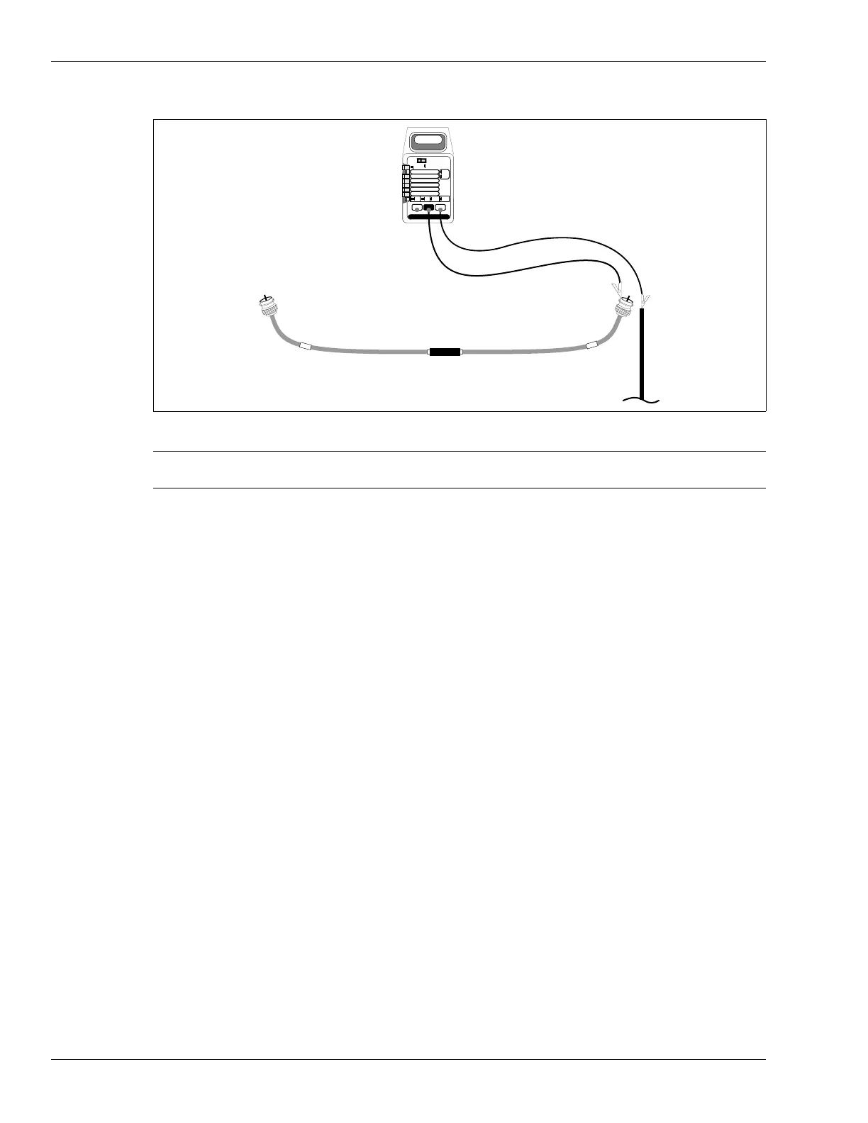
Figure 134: Leakage resistance test
Note During the test do not let the connectors or for SC1 cable, the
conductive black jacket, touch anything that is grounded or each other.
PEAK
HOLD
ON
OFF
DC
AC
TEMP C
2000 mA
200 mA
20 mA
2 mA
200 mV
200¦
2
20
200
1000 DC
750 AC
20M
2000k
200k
20k
2k
200 nS
mA
V
*C
S
¦
mA *C
V ¦
S
multimeter
measure connector shell
(shield) to ground
processor ground rod