Setup
Page 206 OmniTrax Product Guide
Defining the lead-in cable segment as non-detecting
1. Open the sensitivity profile recorded during calibration.
2. Left-click on the Segment Setting window to select the existing Zone.
3. Select the Split button to divide the zone.
The window is divided into two equal portions, one gray and one white.
4. Drag the zone boundary to the start point of the detecting cable.
5. Left-click on the lead-in cable section of the profile.
6. Use the spin controls to select Segment 1 and Zone 0.
7. Save the UCM file and download the configuration data to the processor.
Defining the detecting cable segments
Once you have defined the lead-in cable section as Zone 0 (non-reporting) you can define the
detecting cable according to your site plan. Each time you select the split button, you divide the
selected segment in half. You then adjust the length of the selected segment and assign the
segment’s zone number for alarm reporting. Each processor can include up to 100 cable
segments (50 per cable side) and up to 50 distinct alarm zones (plus zone 0).
1. Left-click on the gray portion of the Segment Setting window (between the lead-in and lead-
out cable sections) to select the detecting cable segment.
2. Select the Split button to divide the segment.
The detecting cable segment is divided into two equal portions, one gray and one white.
3. Drag the zone boundary to the appropriate point of the detecting cable (refer to the site plan).
4. Left-click on the gray detecting cable section of the profile.
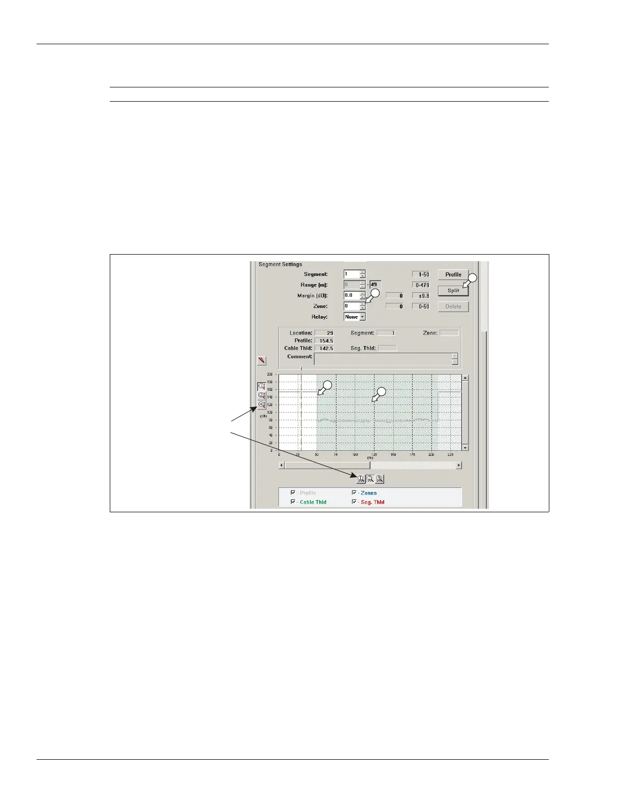
Note You can use the magnification buttons to expand the plot.
Figure 184: Defining cable segments
magnification
buttons:
signal magnitude
cable length