Preparation of trenches
OmniTrax Product Guide Page 115
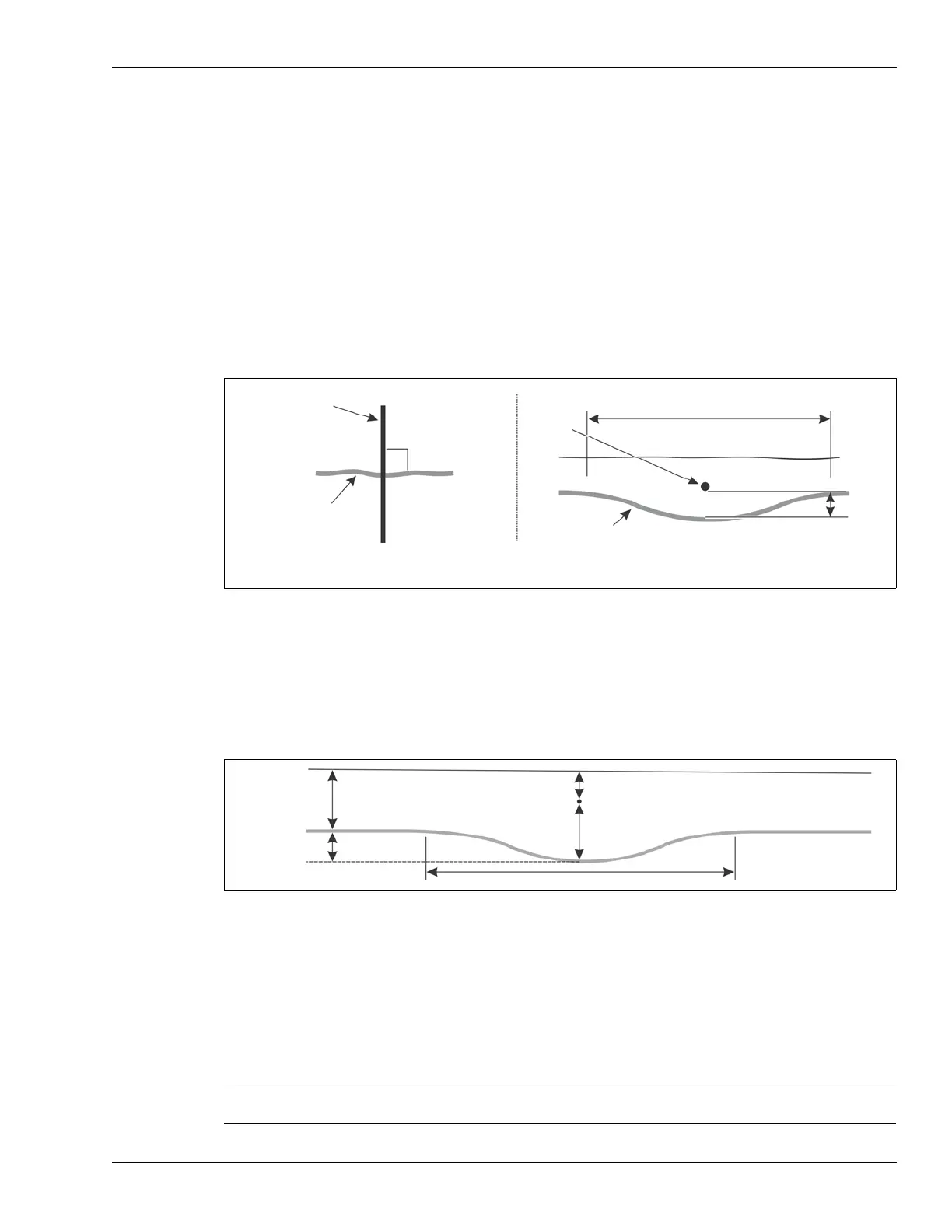
Sensor cable start points
At sensor cable start points:
• the lead-in and detecting cables must cross each other at a 90° angle
• the detecting cable is installed above the lead-in cable, and the detecting and lead-in cables
must NOT touch at the crossover
• for cables buried in soil there must be a vertical separation of at least 23 cm (9 in.) over a short
distance, i.e., the bottom cable (lead-in) must be buried at least 46 cm (18 in.) deep, with the
detecting cable buried at 23 cm (9 in.)
• for cables in hard surface slots there must be a vertical separation of at least 2.5 cm (1 in.)
over a short distance, i.e., the bottom cable (lead-in) must be installed in a 9.5 cm (3¾ in.)
deep slot, with the detecting cable installed above it at 6 cm (2¼ in.)
Detecting cable crossover
If two detecting sensor cables cross, you must raise one cable and lower the other. Change the
burial depths over approximately 1 m (3.3 ft.) using a very gentle slope. For burial in soil, the
required separation between detecting sensor cables is 23 cm (9 in.). For slot installation the
required separation is 4 cm (1.5 in.). The two detecting cables must cross at a 90º angle.
Aligning the lead-in cables
1. Unroll the lead-in cable and lay it in the trench or slot between the start point and the
processor location.
2. Line up the two red bands on the sensor cables side-by-side at the designated start point.
3. Temporarily anchor the sensor cable at the red mark.
Figure 79: Detecting cable / lead-in cable crossover
Figure 80: Detecting sensor cable crossover in soil
Note Use a stake or a flag to mark the location of the red bands on the
ground’s surface.
sensor cable
top view
lead-in cable
90°
sensor
cable
side view
lead-in cable
ground level
46 cm (18 in.)
minimum
a
detecting cable and lead-in cable
must cross at a 90° angle
a = min. 23 cm (9 in.) in soil
a = min. 2.5 cm (1 in.) in concrete/asphalt
11.5 cm (4.5 in.)
23 cm (9 in.)
23 cm (9 in.)
11.5 cm
1 m (3.3 ft.)
ground
level