Cable tests
OmniTrax Product Guide Page 149
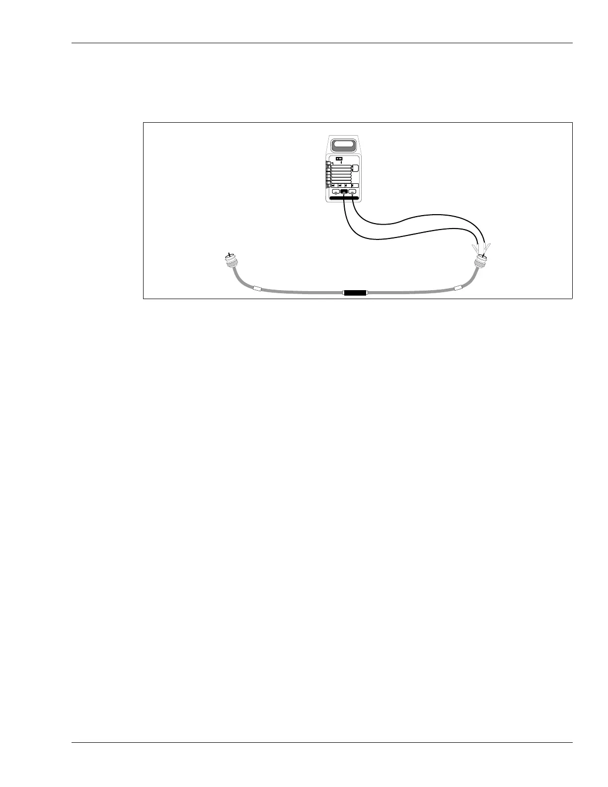
Insulation resistance test
The insulation resistance test ensures that the center conductor is isolated from the outer cable
conductor.
1. Select a sensor cable pair to test. Disconnect both connectors, allowing the connectors to
hang in mid-air during this test.
2. Set a digital multimeter to measure resistance, and attach it to the connector’s center
conductor and shell.
• For cable pairs with network decouplers the resistance should be > 20 M
• For cable pairs with standalone decouplers the resistance should be 130 k 5%
If the resistance is different, there could be a problem with the connector installation or the
decoupler.
3. Reverse the leads and repeat the measurement.
Figure 133: Insulation resistance test
PEAK
HOLD
ON OFF
DC
AC
TEMP C
2000 mA
200 mA
20 mA
2 mA
200 mV
200¦
2
20
200
1000 DC
750 AC
20M
2000k
200k
20k
2k
200 nS
mA
V
*C
S
¦
mA *C
V ¦
S
multimeter
measure connector shell
(shield) to center pin