Installing cable fittings
Page 126 OmniTrax Product Guide
10. Using a heatgun, apply heat evenly across the heatshrink until it fits tightly over the assembly.
The rotating end of the connector MUST turn freely.
11. Verify the connector installation (see Cable tests
on page 146).
Installing connectors on SC1 and SC2 sensor cable
• all connections must be clean and dry - use a heat gun to remove moisture
• do NOT blow on a connector to clean it
• do NOT drop or place the connectors, cable ends, terminators or decouplers on the ground or
allow them to get wet or dirty
• before installing connectors and connecting cables to the processor, cut off the excess lead-in,
ensuring that there is a minimum of 6 m (20 ft.) of lead-in cable and there is enough lead-in
cable to create a 2 m (6.5 ft.) service loop at the processor
Required tools
• SC1/SC2 connector tool kit (P/N A0KT1500) including:
•knife
• large cutting pliers
• small cutting pliers
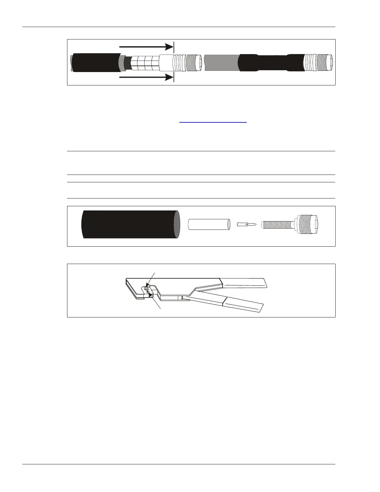
Figure 96: Completing the connector installation
Note The following procedure applies to SC1/SC2 connector parts kit
A0SP0700-003. For SC1/SC2 connector parts kit A0SP0700-002,
follow the instructions (A3DA0403-001) that are included in the kit.
Note Use ONLY the supplied connector kits, and the specified crimp tool with
the SC1 and SC2 cables.
Figure 97: Connector parts kit A0SP0700-003
Figure 98: SC1/SC2 crimp tool
heatshrink
crimp ring
center pin
TNC connector shell
use the large hex opening for the crimp ring
use the small quad opening for the center pin