Installing cable fittings
Page 138 OmniTrax Product Guide
5. Hand tighten each male TNC connector onto a decoupler.
6. Prepare and install connectors on the end of the second sensor cable to match the first sensor
cable.
7. Slide the 71 cm piece of heatshrink over the first cable.
8. Hand tighten the connectors on the second sensor cable to the corresponding decouplers on
the first cable.
9. Test the connections (see Cable tests
on page 146).
10. Apply heat to seal the heatshrink (see Sealing the heatshrink over decouplers/splices
on page
133).
SC1 decoupler installation procedure (method 2 - terminators)
1. Refer to Figure 118: and the site plan to dig trenches or excavate the installation location for
the decouplers.
Note When attaching connectors to decouplers, turn only the connector’s
rotating head shell. DO NOT turn the decoupler.
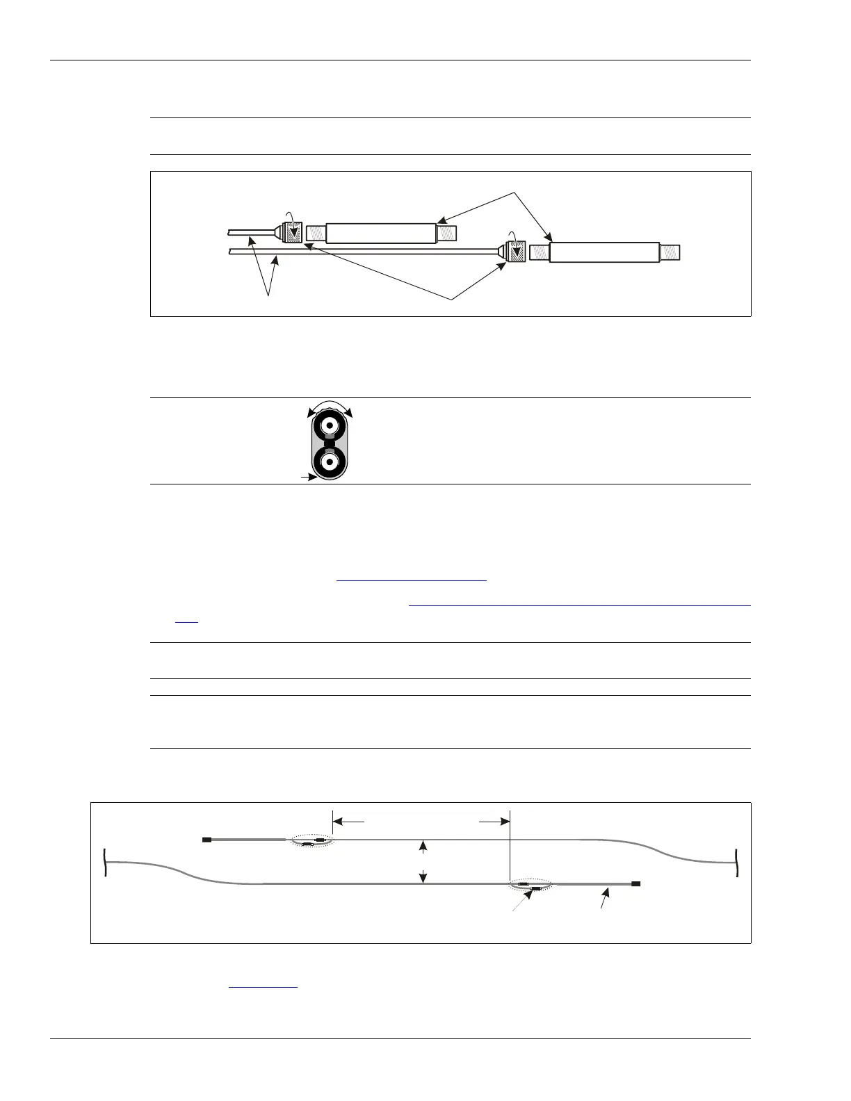
Figure 117: Install decouplers on the first SC1 sensor cable
Note - SC1 Make sure that the ridged surface on the two sensor cables line
up on the same side.
Note At least 5 cm (2 in.) of grey jacket on each side of the connection must
be covered by heatshrink.
Note Ensure that the small sections of heatshrink on the connectors are
completely cooled, before applying heat to the large section of
heatshrink over the decoupler.
Figure 118: Overlapping SC1 cable sets (method 2)
decouplers
first SC1 sensor cable
male connectors
turn the connector shell while
holding the decoupler
smooth
surface
ridged
surface
30 cm (1 ft.) min.
4 m 13 ft.
A-side cable
B-side cable
terminator
standalone decouplers
NOTE: If the two sensor cables are from two processors, the processors must be synchronized via the NICs.