System design
Page 70 OmniTrax Product Guide
System design
The next step is designing the OmniTrax system. The information gathered in the site survey, is
used to select the cable path, the system components, and the components locations. A checklist
has been provided to assist in system design.
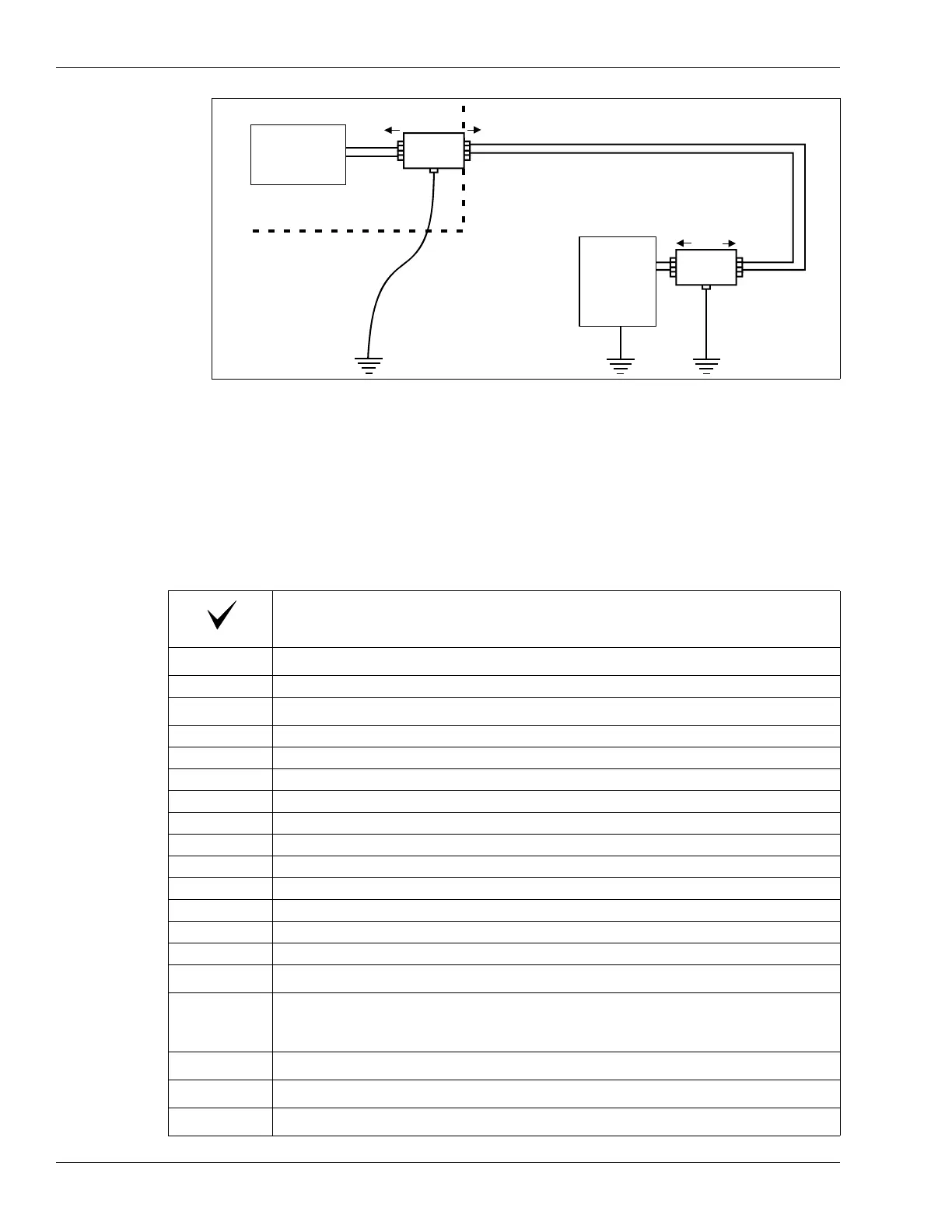
Figure 38: Data link lightning protection
Description
Adjust the proposed cable path to accommodate:
Locations of obstacles
Zone layout details
Indicate total perimeter length, and the beginning and end of the perimeter
Indicate individual cable segments and the length of each segment
Indicate alarm zone boundaries and the length of each zone
Indicate burial mediums along the cable route
Indicate locations, sizes and turn angles of corners
Indicate sensor cable bypasses (hardware/software bypasses)
Indicate burial depth of cables in each zone
Indicate cable spacing in each zone (OC2, SC2)
Indicate start point overlaps
Indicate lead-in cable path to processor
Indicate decoupler/terminator overlap
Equipment locations
Indicate location of processors, decouplers, loopback cables, power supplies,
power distribution, network interface unit, security management system, type and
location of data communication wiring, etc.
Prepare interconnect diagram
List equipment requirements
Prepare revised site drawings
large gauge ground wire
(smooth turns and connected
to a good earth ground)
Network
Interface
Unit
load
line
ground
A
B
lightning arrestor
at building edge
lightning arrestor
at processor
processor
load
line
ground
A
B