Installing a telecom style enclosure
OmniTrax Product Guide Page 87
Installation procedure for telecom enclosures
Preparation
1. Use the site plan to determine the location for the enclosure and dig a hole for the concrete
base.
2. Identify and label all of the lead-in cables and wires.
3. Using the conduit and matching elbows, construct assemblies as required.
4. Protect the conduit by completely covering the openings at both ends of each assembly with
tape.
5. Refer to Figure 52:
Location of conduit assemblies, and install the sensor cable conduit,
auxiliary sensor/data cable conduit, power wiring conduit, and drain pipe.
6. Secure the conduit assemblies by taping the pipes together.
7. Install the ground rod/plate at the processor location.
Note In clay soils with poor drainage, dig the hole about 25% deeper than
specified in the local building code. Fill the additional 25% with clear
crushed stone to aid drainage.
Note PVC pipe assemblies allow the lead-in cables, the optional auxiliary
sensor wiring and data cables, and the power supply connection to run
below ground to the processor. One pipe provides drainage for the
enclosure.
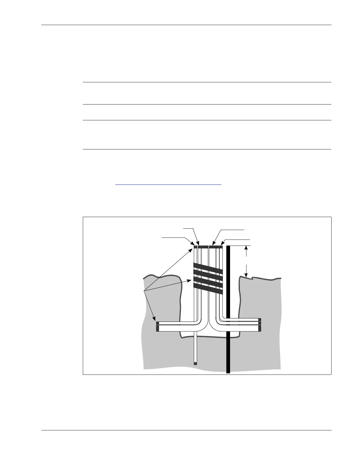
Figure 52: Location of conduit assemblies
drain pipe
tape
lead-in cable
conduit (2X)
power entry
conduit (1X)
ground level
20 cm (8 in.)
auxiliary device/self-test/
data cable conduit