Perimeter layout
OmniTrax Product Guide Page 57
Connected blocks of processors
To provide optical isolation and to prevent the formation of a conductive path around the perimeter,
Senstar recommends that each block of processors with sensor cables that are connected through
decouplers, be limited to a maximum of five processors. Overlapping terminators should be used
at the end of each block of five and the two adjacent processors at each end (e.g., processors 5
and 6) should be connected by a multi-mode fiber optic data link to enable processor
synchronization and data communications. The fiber optic cable can be buried in a trench with the
sensor cable. A block of five processors can cover up to 4 km (2.5 mi.) of perimeter length with
OC2 sensor cable. Figure 35:
illustrates a multi-block example of two optically isolated processor
blocks with five processors in each block.
Sensor cable supervision
The OmniTrax processor supervises the sensor cables. For new installations, cable pair
supervision or clutter supervision are recommended. For retrofit applications using SC1 or SC2
sensor cable and terminators, clutter supervision is recommended. There are three methods for
cable supervision available with the OmniTrax system:
• Clutter Supervision - the current level of clutter on the sensor cables is compared to a
historical clutter level. When a change in the current clutter level exceeds the user-selectable
Historic Variance parameter, a supervision alarm is declared on the cable side.
Clutter supervision is intended for use primarily in OmniTrax retrofit perimeters, (Perimitrax
upgrade - SC1 or SC2 single cable set using standalone decouplers and terminators). It is also
the recommended supervision setting for an unused cable side.
• Cable Pair Supervision - standalone or network decouplers joining two cable sets from two
processors (A-side and B-side). Standalone decouplers join the A-side and B-side sensor
cables on a single processor. With cable pair supervision, the processor transmits error
checking data bits over the connected cables (i.e., TXA to TXB and RXA to RXB). The
processor also monitors and compares the clutter level as described in Clutter Supervision.
• Cable Set Supervision - for legacy installations using standalone decouplers and loopback
cable assemblies at an open ended OmniTrax perimeter (single cable set, TX and RX). With
cable set supervision, the processor transmits error checking data bits over the connected
cables (i.e., TXA to RXA and TXB to RXB). The processor also monitors and compares the
clutter level as described in Clutter Supervision. New installations should use terminators and
Clutter supervision in place of loopback cable assemblies and cable set supervision.
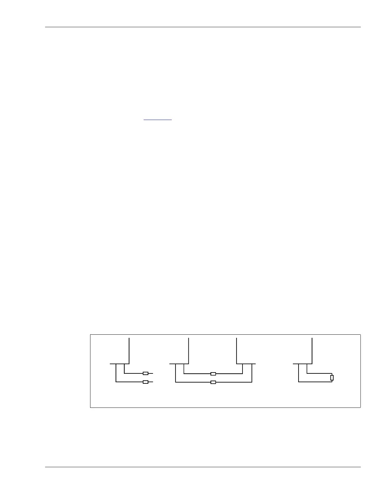
Figure 27: Sensor cable supervision options
open ended perimeter
single cable set
Cable Pair Supervision
joined cable sets
(standalone or network decouplers)
Cable Set Supervision
open ended perimeter
single cable set
Clutter Supervision