Setup
OmniTrax Product Guide Page 207
5. Use the spin controls to select Segment 2 and Zone # (label the zone according to the site
plan; more than one cable segment can be assigned to each zone).
6. Repeat this procedure to define each cable segment and zone, as specified in the site plan.
7. Save the UCM file and download the configuration data to the processor.
Setting the cable segment margins
In addition to the cable margin for the full length of cable, you can also set different cable margins
for each defined cable segment. The cable segment margin is applied as a delta to the full length
cable margin for the selected segment. This can be useful if your site includes any high risk, or low
threat, areas. A wider cable margin in high risk areas will increase the Pd in that area. However, a
wider cable margin can also lead to an increased nuisance alarm rate. For an area where the
threat is considered low, you can decrease the cable segment margin, which will reduce the
chances of nuisance alarms occurring, while still providing an acceptable Pd.
The range of cable margin values for each defined segment is ± 9.8 dB. When you apply a positive
value to a cable segment, you increase the sensor’s sensitivity in that segment. When you apply a
negative value to a cable segment, you decrease the sensor’s sensitivity in that segment. The
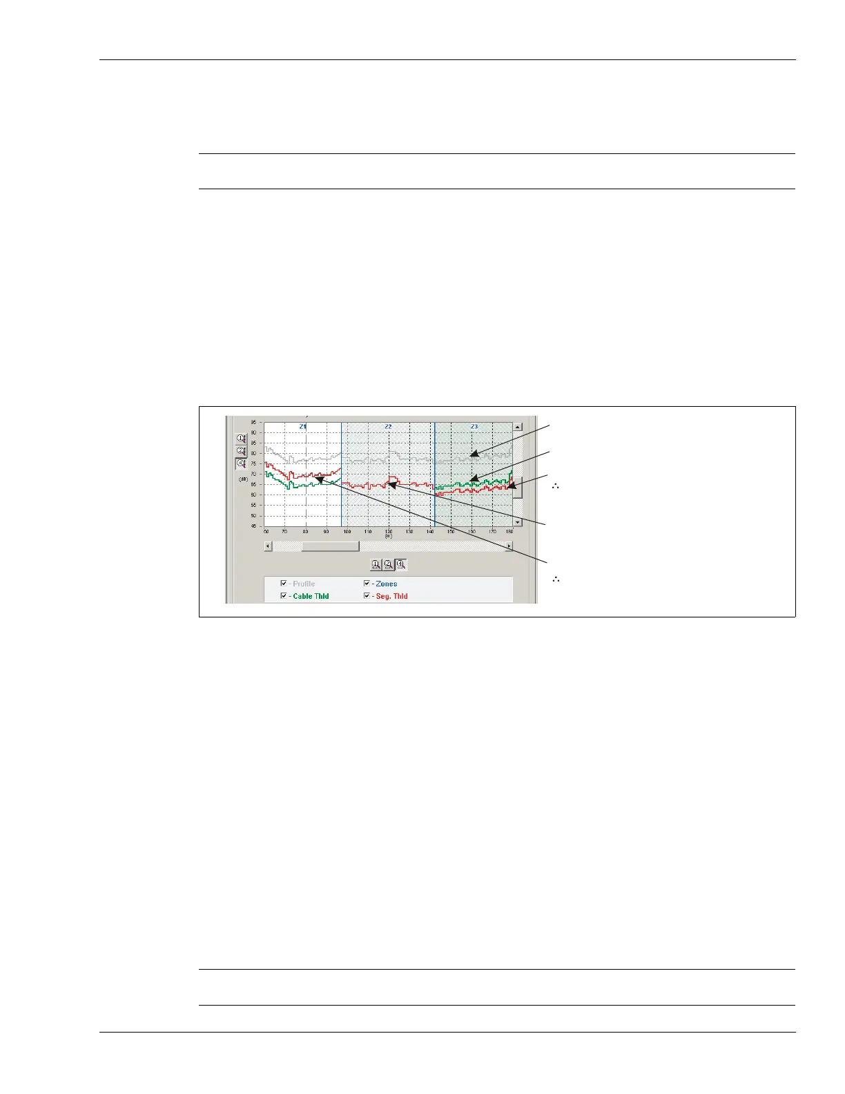
following figure illustrates a cable, which has been split into 5 detecting segments plus the non-
detecting lead-in. Zones 1, 4 and 5 use the default cable margin of 12 dB. Zone 2 has a segment
margin of + 3.8 dB, which is added to the cable margin of 12 dB. This gives Zone 2 a margin of
15.8 dB, making Zone 2 more sensitive to intruders than the other defined zones. Zone 3 has a
segment margin of - 4.5 dB, which is subtracted from the cable margin of 12 dB. This gives Zone 3
a margin of 7.5 dB, making Zone 3 less sensitive to intruders than the other defined zones.
Cable segment margin procedure
1. Select the defined zone to which you will apply a cable segment margin.
2. Use the Margin (dB) spin control to set the cable margin for the selected segment.
3. Save the UCM file and download the configuration data to the processor.
Repeat this procedure to set a cable segment margin for other segments (or Zones) as specified in
the site plan.
Note Any sections of detecting cable that should NOT report alarms must be
assigned to Zone 0.
Figure 185: Cable segment margins
Note Cable segment margins should be set only for zones which require a
higher, or lower, level of sensitivity.
recorded sensitivity profile
cable margin set to 12 dB
Z3 cable segment margin set to 3 dB
3 dB + 12 dB cable margin = 15 dB
alarm threshold for zone 3 (high risk)
Z2 cable segment margin set to 0 (default)
(uses full length cable margin of 12 dB)
Z1 cable segment margin set to -5 dB
-5 dB + 12 dB cable margin = 7 dB
alarm threshold for zone 1 (low threat, or
to reduce a high nuisance alarm rate)