Cable tests
Page 148 OmniTrax Product Guide
Sensor cable tests
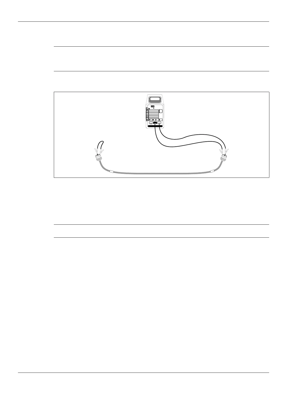
Single cable continuity test
1. At one end of the cable, short the center conductor to the connector shell.
2. At the other end of the cable, measure the resistance between the connector’s center
conductor and shell.
• resistance = 10
or less
Note Perform the single cable continuity test, the insulation resistance test,
and the leakage resistance test before conducting the cable-pair
continuity test.
Repeat each test for all sensor cables.
Figure 132: Single cable continuity test
Note For SC1/SC2 sensor cable the resistance should be approximately 3
per 100 m of cable.
PEAK
HOLD
ON OFF
DC
AC
TEMP C
2000 mA
200 mA
20 mA
2 mA
200 mV
200¦
2
20
200
1000 DC
750 AC
20M
2000k
200k
20k
2k
200 nS
mA
V
*C
S
¦
mA *C
V ¦
S
multimeter
short shield to
center conductor
multimeter
shield to center