The OmniTrax enclosure
OmniTrax Product Guide Page 85
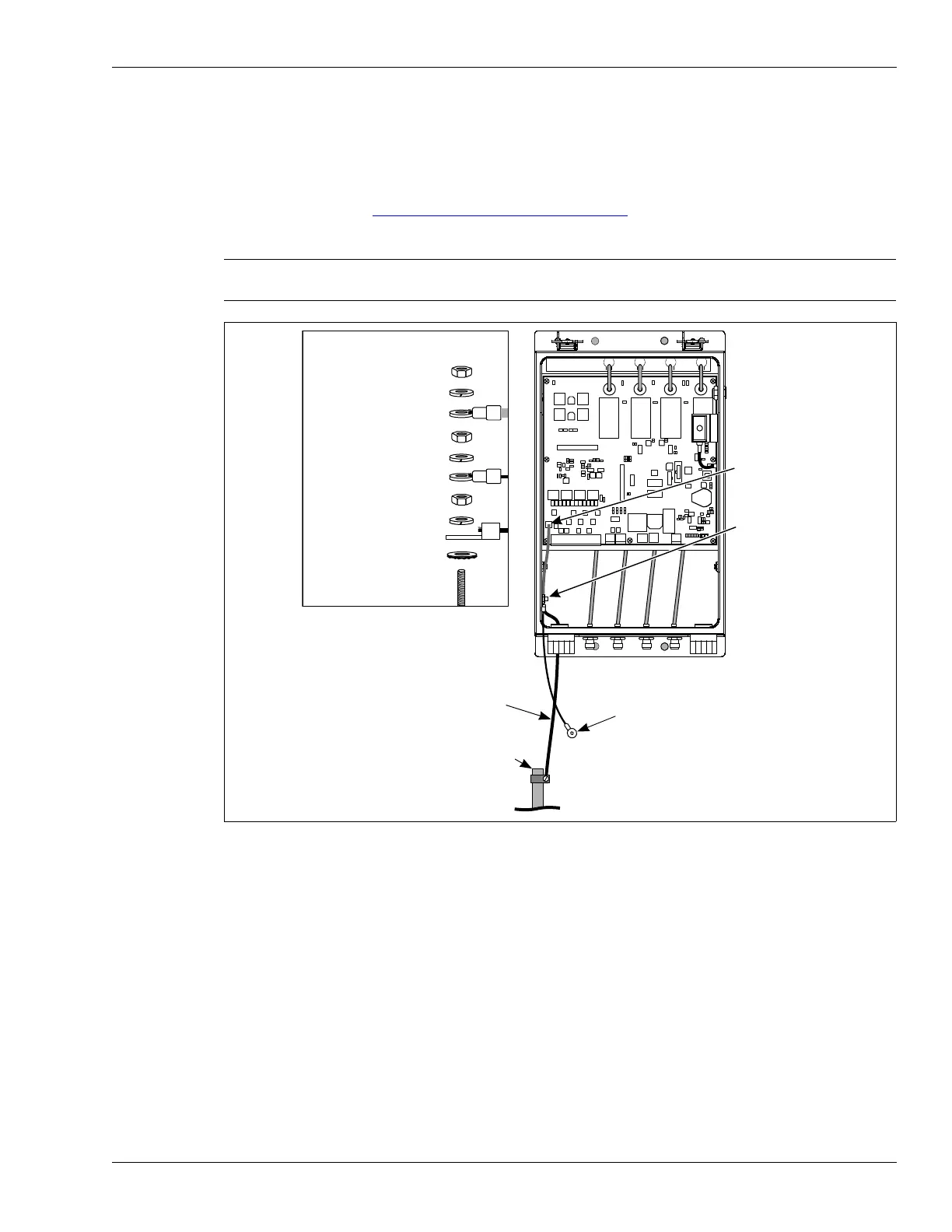
System grounding
The OmniTrax processor requires a connection to a low resistance earth ground (Senstar
recommends 5
or less). Install an approved ground rod or ground plate as close to the processor
as possible. Use an approved ground wire to connect the ground rod to the ground lug on the
processor enclosure. Figure 50:
Ground connection details illustrates the OmniTrax earth ground
connection.
Points to remember
• follow all local construction and electrical codes
• install the enclosure above the high water and high snow levels
• install anti-ram bollards in areas with vehicle traffic
• ensure the cable glands and TNC connectors on the bottom of the enclosure are oriented
toward the ground
Note Consult the local electrical code for information about installing a low
resistance earth ground.
Figure 50: Ground connection details
T5
K3 K4
K1
J1
T1
T7
T3
RXBRXA
+
F2
TXB
RELAY 3
RELAY 4
+
BOOT FAIL
RESERVED
+
J
A
M
A
-
RELAY 1
RELAY 2
RE
LA
Y
2
R
ELA
Y
1
-
R
EL
A
Y 4
ISR
A4BA0100-___
REV A
J
A
M
B
A
DC OV
E
RF
LO
W
INPUT POWER
BATTERY 6V
+
BATTERY FAIL
DOOR OPEN
RE
LA
Y
3
INTERN AL POWER FA IL
NETWORK POWER FAIL
ground connection details
hex nut
split lock washer
PCB ground
hex nut
split lock washer
enclosure door ground
hex nut
split lock washer
earth ground lug
external tooth washer
enclosure ground stud
PCB ground
earth ground
connection
(enclosure
ground stud)
ground wire
to ground rod
ground rod
enclosure
door ground
(door not shown)