Cable splices
Page 144 OmniTrax Product Guide
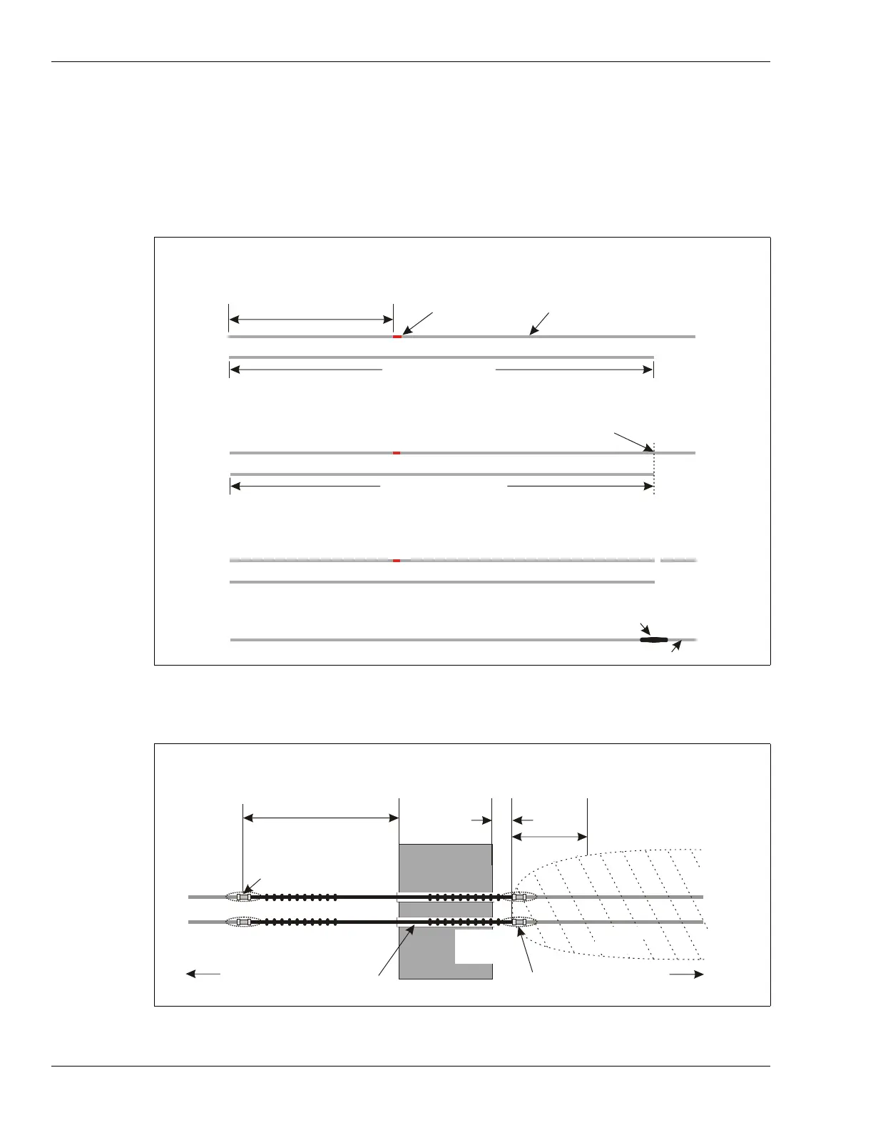
Splicing in additional SC1/SC2 lead-in cable (greater than 15 m)
To add more than 15 m of lead-in cable, you must remove an equal amount of detecting cable from
the start-up section of cable, which is marked by the red band. The following figure illustrates an
example where site conditions require 50 m of lead-in cable. Therefore, the first 30 m of detecting
cable from the startup section (past the red band) and the existing 20 m of lead-in cable must be
cut out. A 50 m section of replacement lead-in cable is then spliced in at the 30 m point, where the
detecting cable was cut.
Sensor cable bypasses - hardware bypass
Figure 126: SC1/SC2 lead-in splice
Figure 127: Sensor cable hardware bypass
1. Layout the SC1 or SC2 sensor cable.
2. Determine the amount of additional lead-in cable that is required.
3. Obtain the necessary amount of lead-in cable and lay it out beside the original cable.
20 m of integral lead-in
red band
detecting cable
50 m lead-in cable
4. Cut the original cable past the red band to match the length of the replacement
lead-in cable.
50 m lead-in cable
cut the original cable to match
5. Label and retain the cut-out lead-in and detecting cable.
20 m lead-in
first 30 m detecting cable
6. Splice the 50 m lead-in cable onto the remaining detecting cable.
splice
50 m of lead-in cable
detecting cable minus 30 m
7 m (23 ft.)
(12 in.)
4 m (13 ft.)
obstacle
required section of non-detecting cable = 7 m + width of obstacle + 30 cm
required section of detecting cable removed = 7 m + width of obstacle + 30 cm
required software bypass = 7 m + width of obstacle + 30 cm + 4 m
bypass start point
(cable splice)
30 cm
detection field requires 4 m (13 ft.)
to build up to full strength
detecting
conduit through obstacle
to processor to decouplers
bypass end point
(cable splice)
ferrite
beads
cable
detecting
cable