Setup
Page 212 OmniTrax Product Guide
define the inputs as normally open (NO) or normally closed (NC) with single resistor supervision,
dual resistor supervision, or unsupervised. A Filter Window parameter allows you to set the time
period for which an input must be active, before the processor reports an event.
Local control mode
In local control mode, the two AUX I/Ps on the OmniTrax processor are self-test inputs. When
there is a momentary switch input to an AUX input, the processor compares the current clutter
level to the recorded historic clutter level on the respective cable side (AUX1 = A side cable,
AUX2 = B side cable). If the current clutter level is within the Historic variance parameter
(default = 12 dB) of the historic clutter level, the processor activates all relays that are assigned to
the cable side. AUX1 activates all relays that are assigned to Side A. AUX2 activates all relays that
are assigned to Side B. If the current clutter level deviates from the historic clutter level by more
than the Historic variance parameter, the relays do not activate (self-test fails).
Remote control mode
In remote control mode, the two AUX I/Ps on the OmniTrax processor, and the eight inputs on the
UIC (if installed) serve as auxiliary device inputs to the host security management system. The
inputs are available for reporting the status of other security devices. The processor reports any
change of an input’s state to the host system, via the Silver Network.
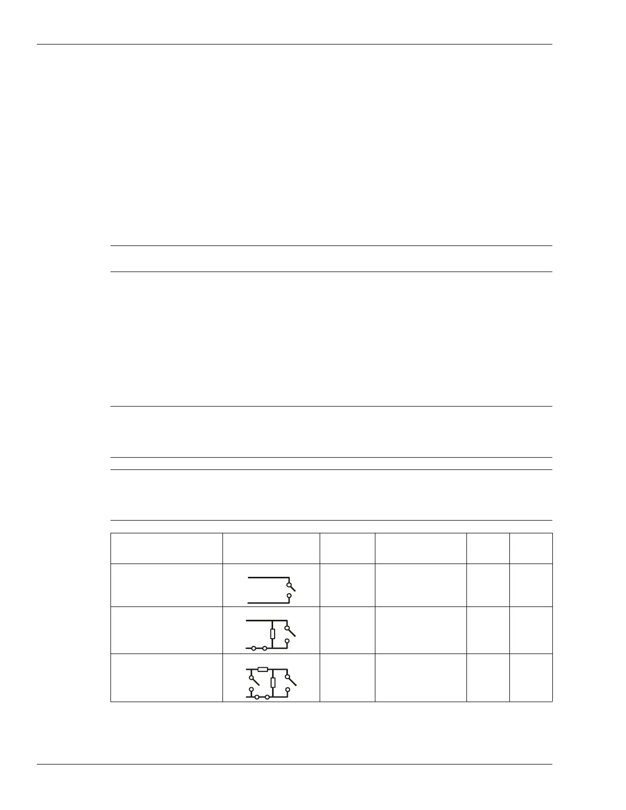
Input wiring configurations
Note The momentary switch input must be held for the period specified in the
Filter Window parameter (default = 250 ms).
CAUTION Use 1%, ¼ W supervision resistors for OmniTrax inputs. When
selecting resistor values, there must be sufficient voltage threshold
margins for the processor to discriminate between alarm and tamper
conditions.
Note Senstar recommends the standard UCM selectable resistor
configurations, which provide optimum alarm and tamper thresholds.
Contact Senstar Customer Service if you require a supervision resistor
configuration that is not available through the UCM menus.
Input option UCM selection Alarm
relay
Supervision relay R1 R2
unsupervised NO --- --- ---
single resistor
supervision
NO NC 5.1 k ---
dual resistor
supervision
NO NO/NC 4.3 k 820
UCM selectable input configurations (with standard resistor values)