Network communication
Page 178 OmniTrax Product Guide
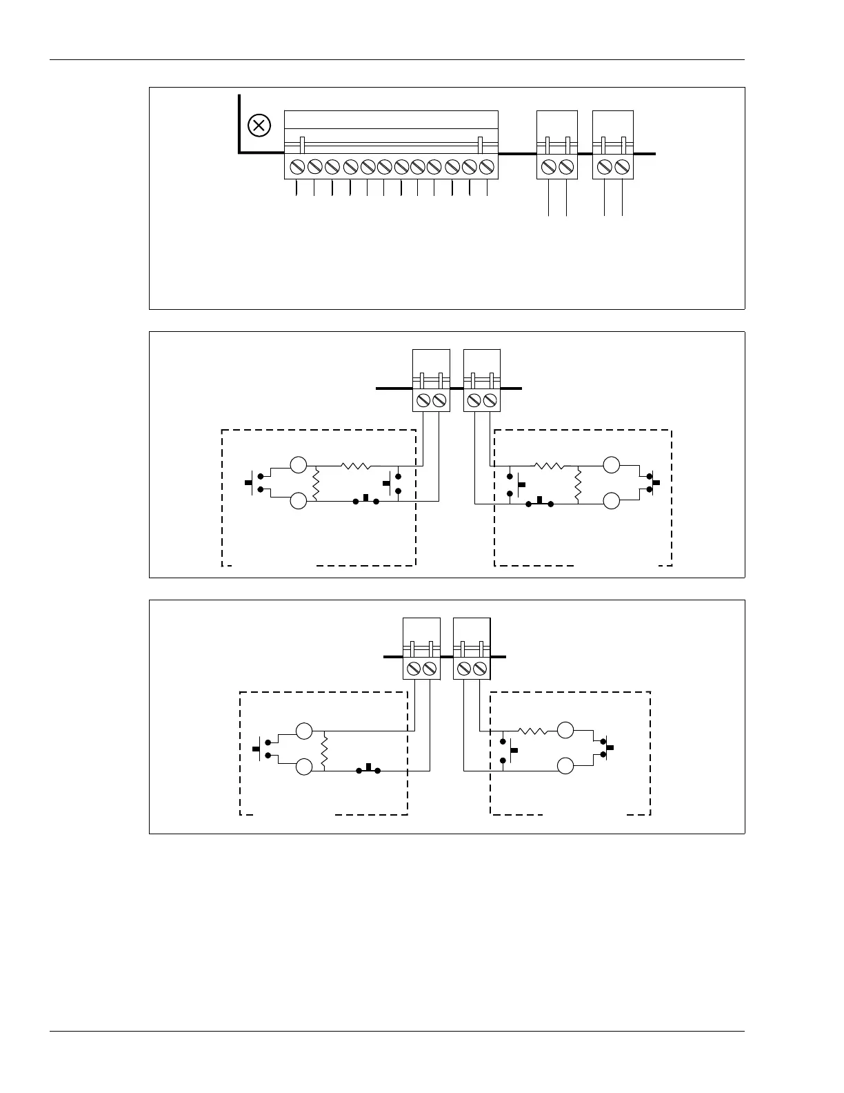
Figure 156: Remote control mode output relay and auxiliary input wiring
Figure 157: Auxiliary device inputs (dual resistor supervision)
Figure 158: Auxiliary device inputs (single resistor supervision)
AUX 2
AUX 1
O
/
P
p
o
i
n
t
1
-
K
1
N
C
O
/
P
p
o
i
n
t
1
-
K
1
C
O
M
O
/
P
p
o
i
n
t
1
-
K
1
N
O
O
/
P
p
o
i
n
t
2
-
K
2
N
C
O
/
P
p
o
i
n
t
2
-
K
2
C
O
M
O
/
P
p
o
i
n
t
2
-
K
2
N
O
O
/
P
p
o
i
n
t
3
-
K
3
N
C
O
/
P
p
o
i
n
t
3
-
K
3
C
O
M
O
/
P
p
o
i
n
t
3
-
K
3
N
O
O
/
P
p
o
i
n
t
4
-
K
4
N
C
O
/
P
p
o
i
n
t
4
-
K
4
C
O
M
O
/
P
p
o
i
n
t
4
-
K
4
N
O
AUX 1
I/P point 1
AUX 2
I/P point 2
dual resistor supervision
normally open alarm relay
normally open OR normally
closed tamper relay
dual resistor supervision
normally open alarm relay
normally open OR normally
closed tamper relay
AUX 1
AUX 2
alarm relay
(NO)
alarm relay
(NC)
supervision
relay (NO)
OR (NC)
supervision
relay (NO)
OR (NC)
auxiliary deviceauxiliary device
single resistor supervision
normally open alarm relay
normally closed tamper relay
single resistor supervision
normally closed alarm relay
normally open tamper relay
AUX 1
AUX 2
alarm relay
(NO)
alarm relay
(NC)
supervision
relay (NC)
supervision
relay (NO)
auxiliary device
auxiliary device