Page 166 OmniTrax Product Guide
1. Press fit the auxiliary power supply onto the enclosure door.
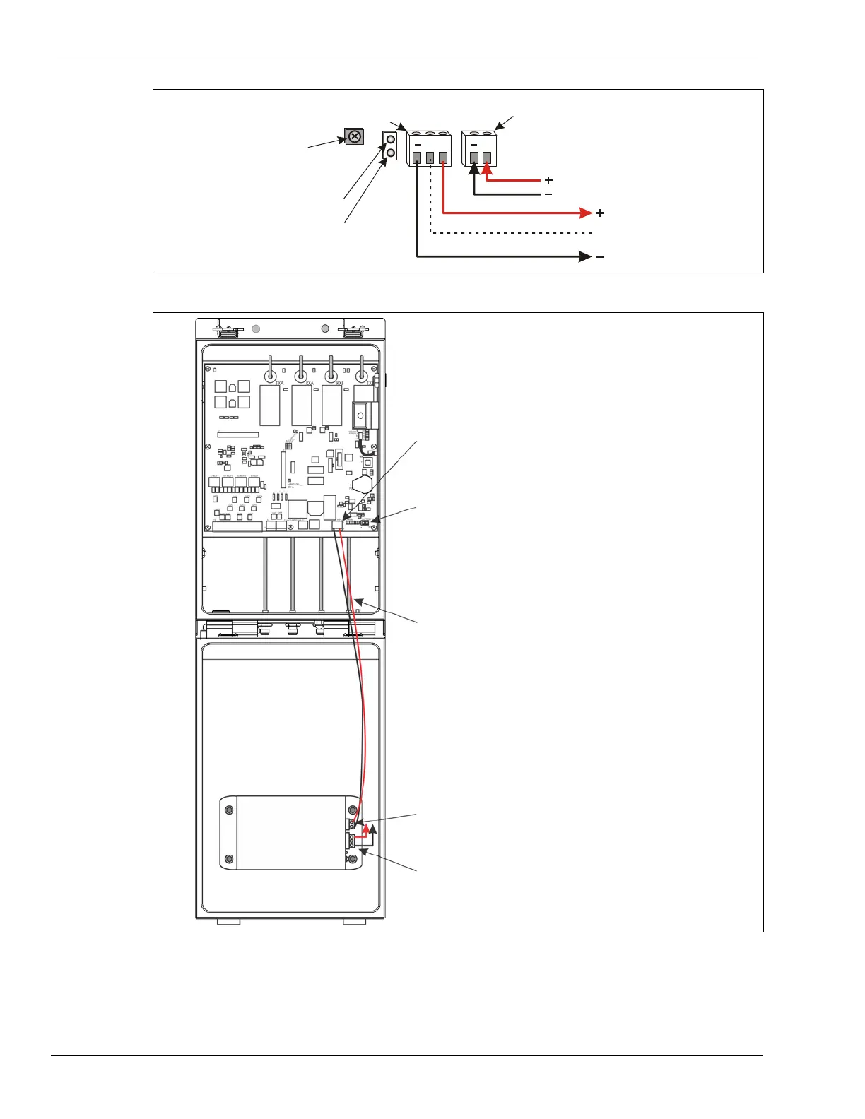
2. Make the wiring connections as indicated above.
Figure 145: Auxiliary power supply wiring
Figure 146: Auxiliary power supply module
connect to auxiliary
security device
connect to enclosure
door ground stud
connect to power connector
(T3) on OmniTrax processor
OR
48 VDC network power supply
VDC
VDC
no connection
OBSERVE POLARITY
12 VDC output
power LEDs
48 VDC input
12 VDC
48 VDC
output
input
VDC
VDC
T3 - 48 VDC network power output to auxiliary power
supply (processor MUST receive 48 VDC over the sensor
cables)
T4 - battery connection (- +)
48 VDC network power output leads (red = +, black = -)
12 VDC @ 150 mA power output to auxiliary device
auxiliary power
supply
48 VDC network power input to auxiliary power supply
(red = +, black = -)