B-13
The LCD card has five hardware points associated with it. Only the first three
hardware points (user LEDs) on the LCD card can be programmed by the user.
The labels for the points on the LCD card are default labels, and cannot be
changed by the user. The following table describes the points included on the
LCD card.
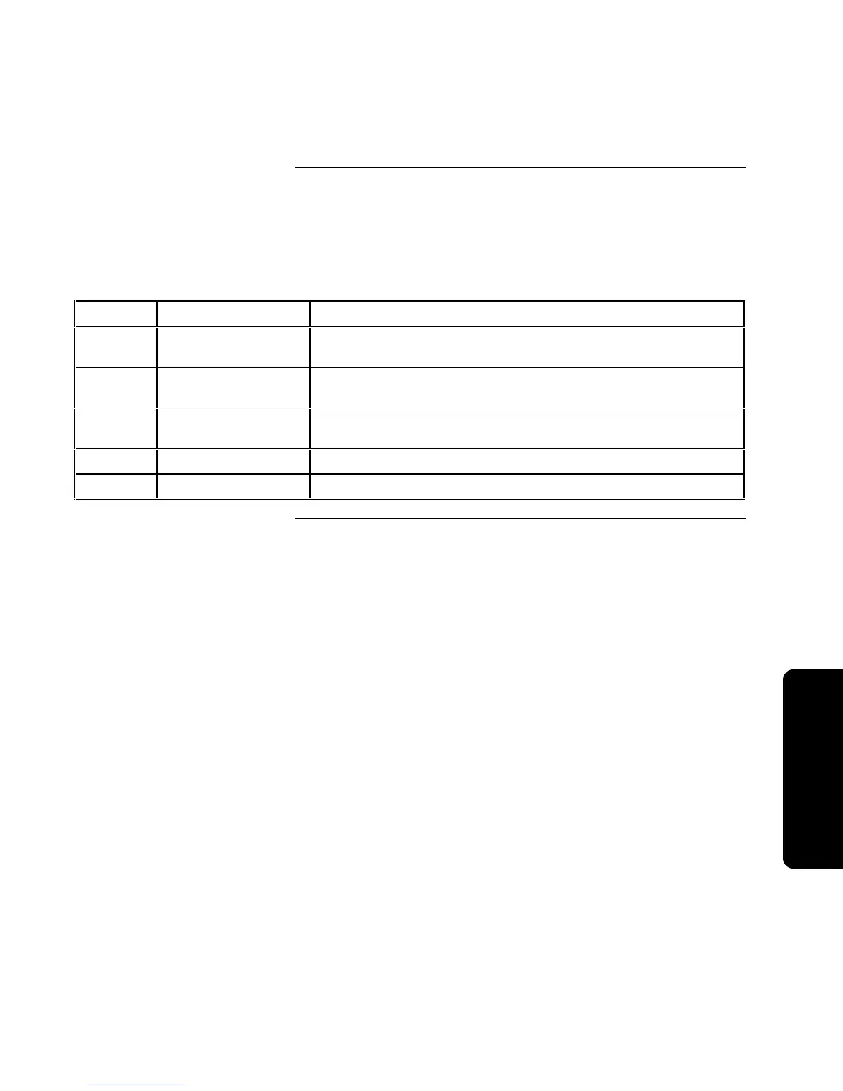
Table B-17. Points on the LCD Card
Point Label Description
Card-1 LCD Card #, Point 1 The status of the First User LED on the LCD card. Programmable
for color and mode.
Card-2 LCD Card #, Point 2 The status of the Second User LED on the LCD card.
Programmable for color and mode.
Card-3 LCD Card #, Point 3 The status of the Third User LED on the LCD card. Programmable
for color and mode.
Card-4 LCD Card #, Point 4 The status of the Alarm Silence LED on the LCD card.
Card-5 LCD Card #, Point 5 The status of the Piezo Sounder on the LCD card.
Hardware Points, Continued
LCD Points
Hardware/Pseudo Points
Technical Manuals Online! - http://www.tech-man.com