3-3
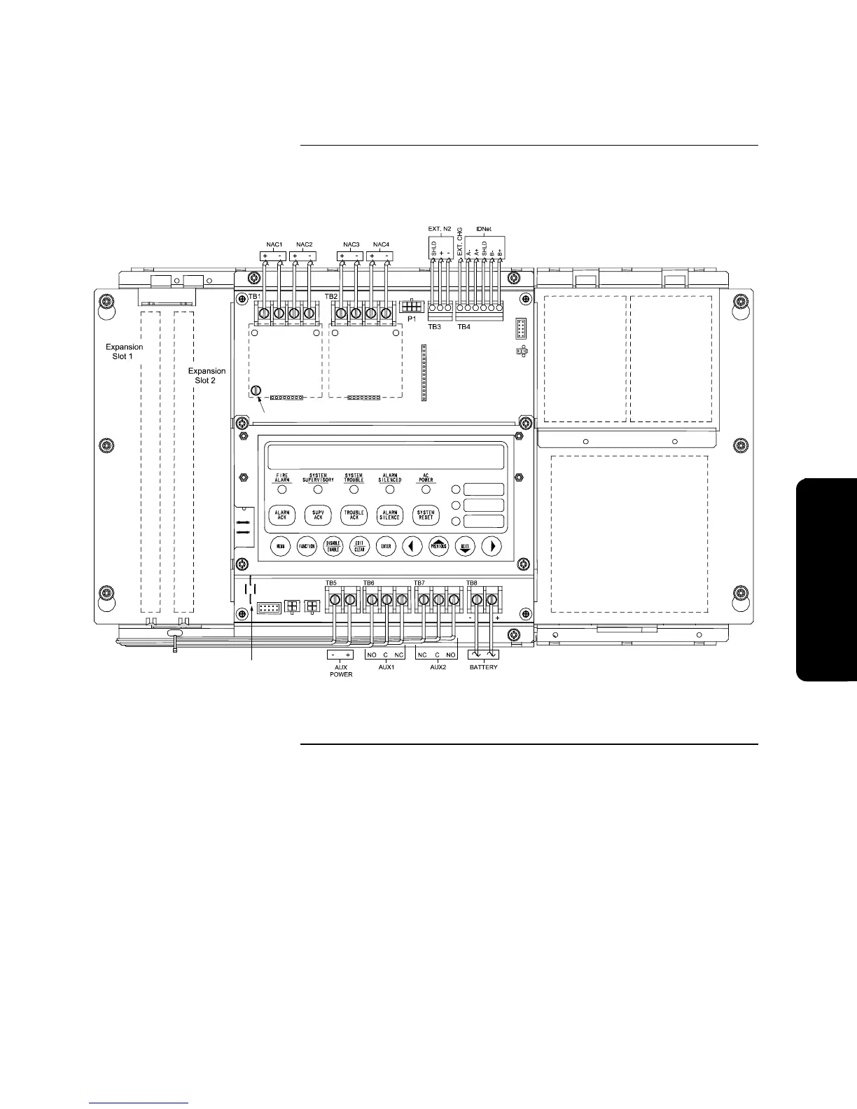
Figure 3-2 shows the location of all terminal connections for the system
components. Refer to the appropriate section later in this chapter for specific
information on wiring a component.
4010-9813
Expansion Power
Supply (565-792)
or
4010-9814
Supression Power
Supply (565-793)
4010-9809
City Module
4010-9820
Battery Meter
Module
4010-9806
Class A
Module
(565-789)
Pot for LCD Adjustment
4010-9806
Class A
Module
(565-789)
WARNING: PTCs MUST NOT TOUCH EACH OTHER OR
ANY OTHER METAL SURFACE!
Figure 3-2. Base Panel Wiring
Overview, Continued
Locations of Terminal
Connections
Wirin
Technical Manuals Online! - http://www.tech-man.com