8-10
Version 2.01 or later of the 4010 system supports up to 60 Custom Control
equations. A Custom Control equation consists of up to six statements. Each
equation consists of two sides: an INPUT SIDE and an OUTPUT SIDE. An
equation can be better understood as an “IF/THEN” command. “IF” the INPUT
SIDE is true, “THEN” execute the OUTPUT SIDE.
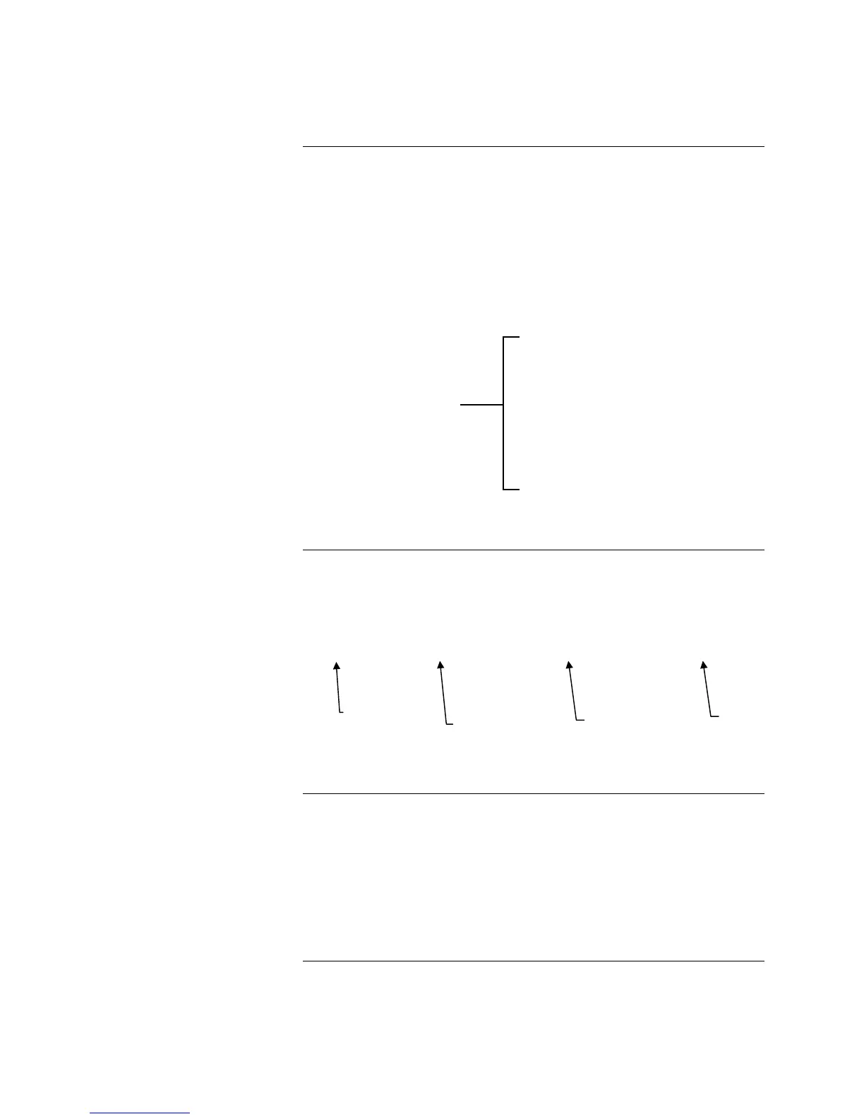
Each equation is made up of one or more input statement and one or more output
statement (for a total of six statements). The equation in Figure 8-4 has four
statements: two input statements and two output statements.
Equation
Input Statement
Input Statement
End of Inputs
Output Statement
Output Statement
End of Outputs
Figure 8-4
Each input statement is made up of four fields.
[ ] [NOT] [FIRE] [3-01]
Figure 8-5
Field 1 is always empty in the first statement of any Custom Control equation.
In subsequent statements, Field 1 will contain one of the two Link operators:
• AND which links the statement in “Series” with all previous
statements
• OR which links the statement in “Parallel” with all previous
statements.
Continued on next page
Custom Control Programming, Continued
Equations
Input Side (IF)
Field 1
Empty field
starts a Custom
Control
equation input
Optional NOT
operator
Field 1 Field 2 Field 3 Field 4
FIRST
STATEMENT
Condition qualifier
for field 4
Point
Technical Manuals Online! - http://www.tech-man.com