3-9
The 4010 provides two auxiliary (AUX) relay circuit connections; one at TB6
and the other at TB7. Each circuit provides one form “C” contact (normally
open or normally closed) rated at 2A (24VDC), or 0.5A (120 VAC) with
optional 120 Volt auxiliary relay kit.
The default operation for AUX1 is an Alarm Relay and AUX2 is a Trouble
Relay. The AUX relay circuits can also be programmed for other desired
operations using the front panel (see “Chapter 6 - Configuring Points”).
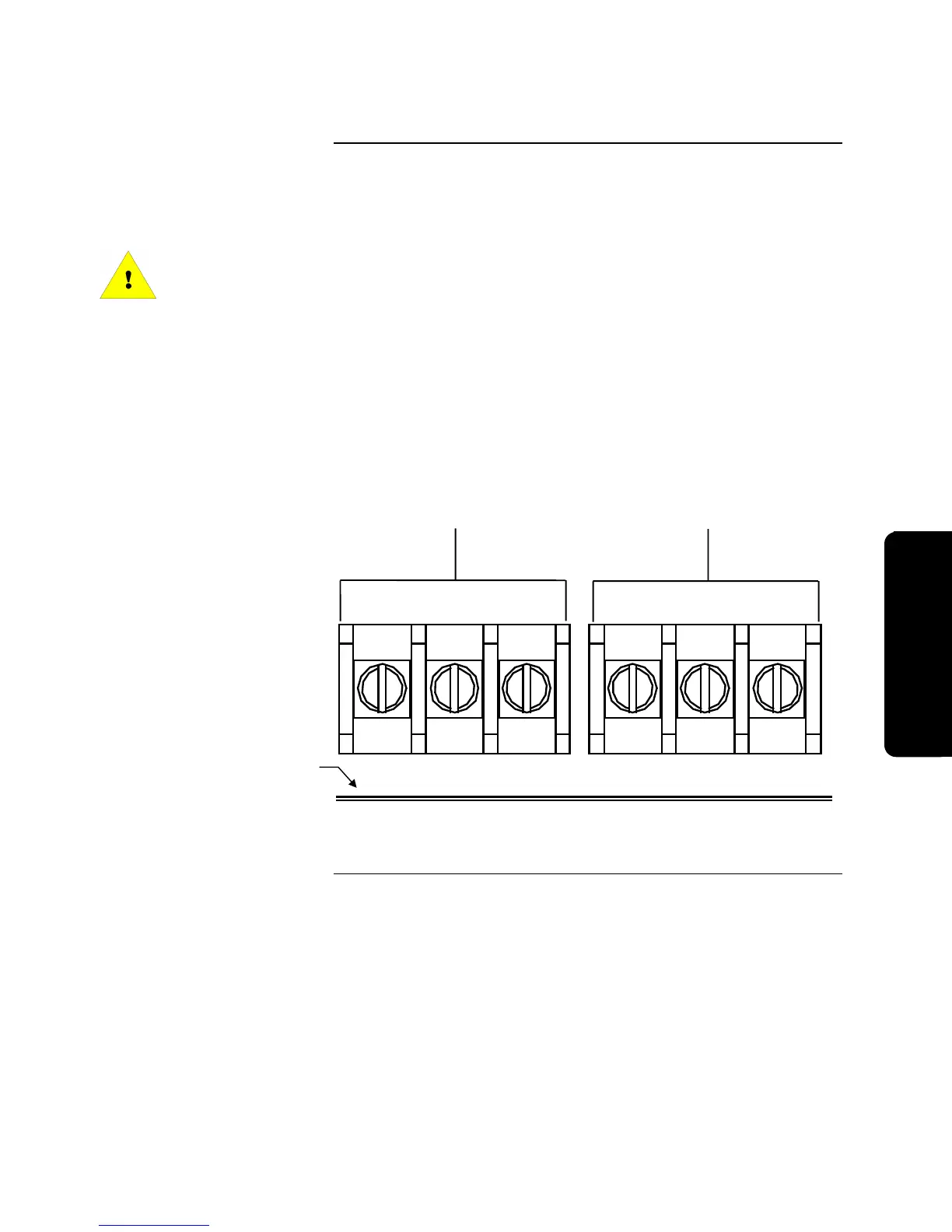
Use Figure 3-8 to wire the AUX relay circuits. TB6 and TB7 are located at the
bottom of the SFI/O near the center.
When power for the AUX relay contacts is from TB5 (AUX Power), 4010-9813,
or 4010-9814 expansion power supplies, the circuit is power-limited. When
power for the AUX relay contacts IS NOT from the sources listed above, use an
in-line fuse (Part No. 208-165). If power source is non-power-limited, wiring
must be routed through the non-power-limited spaces shown in Figure 3-1 and
“power-limited” markings must be obliterated.
Figure 3-8. AUX Relay Connections
Auxiliary Relays
Auxiliary Relays
Bottom of the SFI/O
TB6 TB7
NO C NC
AUX1 AUX2
NC C NO
Wirin
Technical Manuals Online! - http://www.tech-man.com