4 Operation
Auxiliary equipment
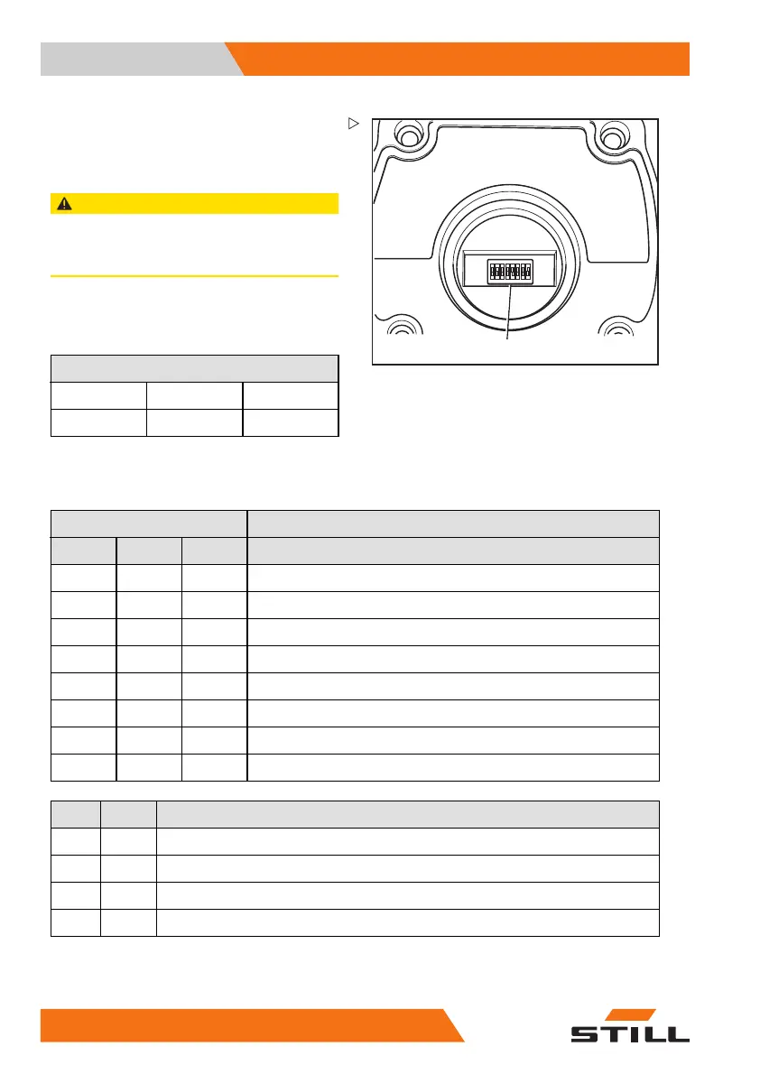
12345678
3
– Using the DIP switches "1" to "5" (3), adjust
the range and the sensitivity of the sensor.
The DIP switches can be adjusted using a
small screwdriver.
CAUTION
The settings for DIP switches "6" to "8" are the
factory settings of the manufacturer.
They must not be changed!
Factory settings of the manufacturer - do not
change
DIP switch
6
7
8
110
The possible settings for DIP switches "1" to
"5" are shown in the following tables:
DIP switch
123
Range
000 2m
001 3m
010 4m
011 6m
100 8m
101 12m
110 16m
111 24m
45
Sensitivity
00
Very high
01
High
1 0 Medium
11 Low
The sensor has different beam angles de-
pending on the combination of range and
262
56368011531 EN - 06/2019 - 02
 Loading...