52
2. INSTALLATION
When you select "IR control" as the connection type and click the [ ] but-
ton at the right, the test signal is sent to the visual acuity chart. This function
is convenient when checking that communication can be executed correctly
by the selected channel.
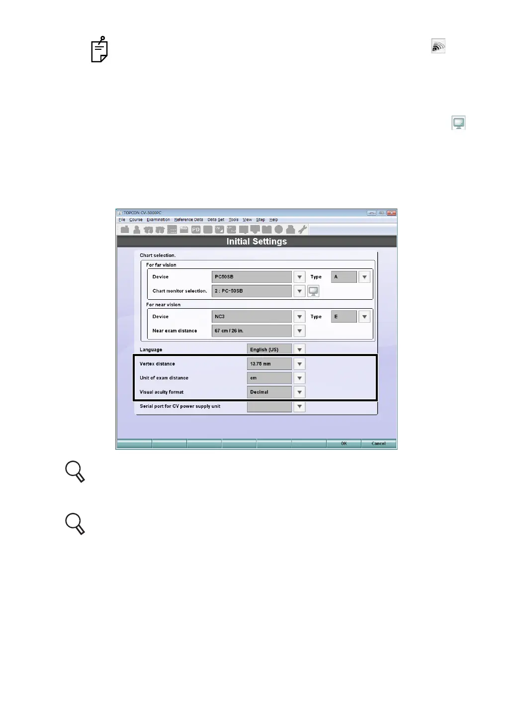
When you select "PC-50S", "PC-50SB" or "MC-4S" from the far-point chart
devices, "Interface" is changed to "Chart monitor selection". Click the [ ]
button at the right. You can check the monitor that corresponds to the name
in the "Chart monitor selection" list being displayed.
3 elect proper values for "Vertex distance", "Unit of exam distance" and "Visual acuity for-
mat".
"Vertex distance" and "Unit of exam distance" can also be set by "General settings".
For the details of each item, refer to P.167 ("Vertex distance") and P.168 ("Unit of exam
distance").
"Visual acuity format" can also be set by "Chart settings". For the details, refer to
P.177.
 Loading...