4: INSTALLATION
Required Tools 101
Prepare the Machine 101
Remove the Right Side Window 101
Remove the Operator Box 101
Install the Mount Arm 101
Mount the Console 102
Assemble the Controller and Keyboard Tray 102
Lift and Secure the Controller Assembly 104
Make Electrical Connections 105
Reassemble the Machine 107
PathPilot Operator Console Drill Template 108
Required Tools
This procedure requires the following tools. Collect them
before you begin.
l 15/64 in. drill bit
l Electric drill
l Hole punch
l Level
l Metric hex wrench set
l Phillips screwdriver
l Phillips screwdriver, small
l Scissors
l Ruler
l Tape
Prepare the Machine
1. Power off the machine and the PathPilot controller.
a. Push in the machine's red Emergency Stop button,
which removes power to motion control.
b. From the PathPilot interface, select Exit.
c. Turn the Main Disconnect switch to OFF on the side
of the electrical cabinet.
2. Close the enclosure doors.
NOTICE! This procedure requires you to drill four
holes into the enclosure. If the enclosure's right
door is open, there's a risk that you'll drill into it.
Remove the Right Side Window
To make it easier to install the mount arm, we
recommend removing the right side window from the
enclosure. Loosen the screws on the vertical window
retainers, and slide the window out of the right side
panel. Set the window aside.
Remove the Operator Box
1. Remove the Emergency Stop cable from the operator
box.
2. Remove the four screws that secure the operator box to
the machine stand using a 3 mm hex wrench.
Discard the operator box.
3. Put the four screws from the operator box back on to the
machine stand.
Install the Mount Arm
1. Print the drill template provided in this document. To
verify that the template printed at the correct size, use a
ruler to measure the 1 in. scale on the template. If the
template is incorrectly sized, adjust your printer settings
and try again.
2. Cut out the drill template along its edges.
3. Find the operator console's mount arm.
4. Put the drill template on the mount arm's top bracket.
Then, verify that the holes on the bracket align with the
holes on the drill template. If they don't, trace the
correct hole pattern on to the drill template.
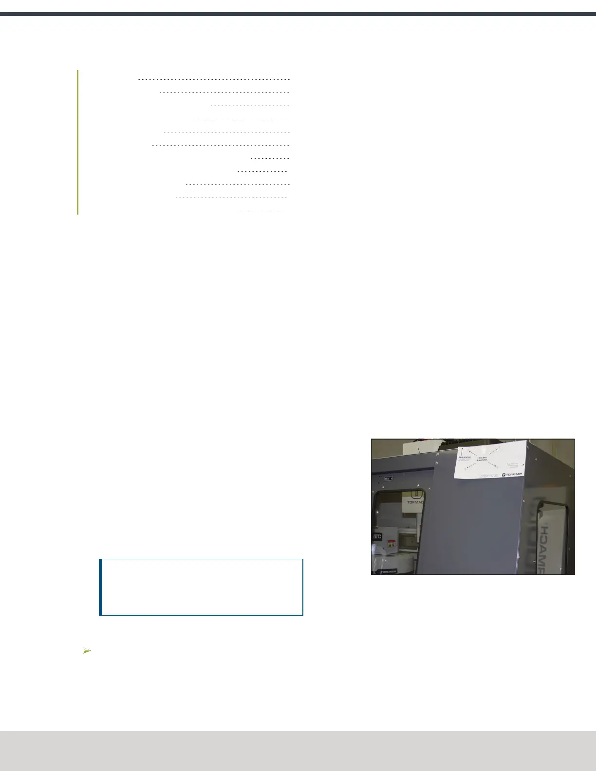
5. Align the drill template to the top of the enclosure and
tape it in place, as shown in the following image.
Figure 4-174: Drill template taped to the enclosure.
6. Put a mark in each hole on the drill template using a
hole punch.
7. Remove the drill template from the enclosure and
discard it.
©Tormach® 2023
Specifications subject to change without notice.
Page 101 Tormach 1100M® Operator's Manual (Version 1223A)
For the most recent version, see tormach.com/support