6. Remove the hex head screw on the Power Drawbar
cylinder’s rod with an adjustable wrench, and set it
aside.
Figure 4-95: Hex head screw on the Power Drawbar
cylinder's rod.
7. Remove the M16 washer from the Power Drawbar
cylinder’s rod, and set it aside.
Figure 4-96: M16 washer removed from the Power
Drawbar cylinder's rod.
8. Put the hex head screw back in, and then tighten it
completely with an adjustable wrench.
9. Pivot the Power Drawbar cylinder to the original location.
10. Push in the quick-release pin.
11. Reconnect the shop's air supply to the Power Drawbar
button.
12. Examine the space between the hex head screw on the
Power Drawbar cylinder’s rod and the top of the
drawbar.
13. Verify that the gap is between 3/64 in. and 1/8 in. (1
mm and 3 mm). Depending on the size of the gap, do
one of the following:
l
Between 3/64 in. and 1/8 in. (1 mm and 3 mm)
You have completed adjusting the initial setup.
l
Less Than 1/8 in. (1 mm) Go to Step 14.
14. Find the three provided M14 flat washers.
15. Put one M14 flat washer under each mounting post on
the Power Drawbar cylinder.
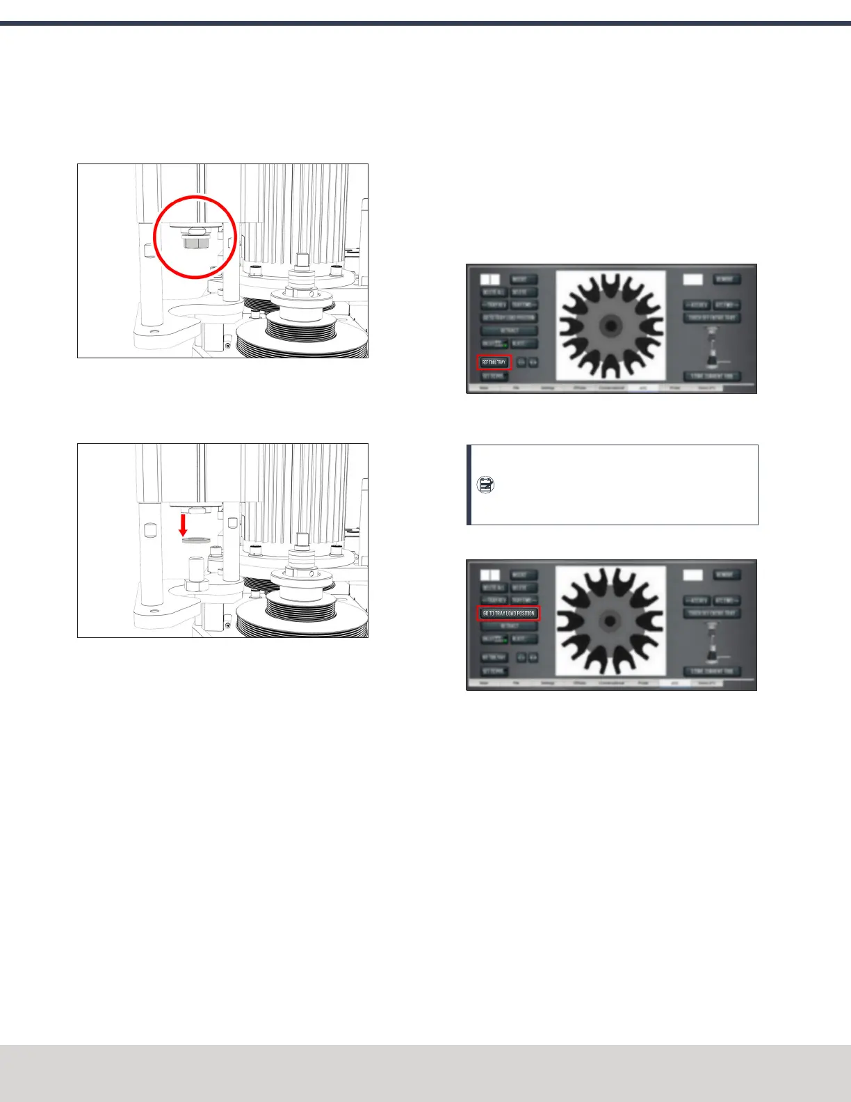
Adjust the Tool Tray Load Position
1. Verify that there's no tool in the spindle.
2. From the PathPilot interface, on the ATC tab, select Ref
Tool Tray.
Figure 4-97: Ref Tool Tray button on the ATCtab.
The tool tray spins.
Note: You're only required to reference the tool
tray once, unlike the mill axes’ referencing
procedure.
3. Select Go to Tray Load Position.
Figure 4-98: Go to Tray Load Position button on the
ATC tab.
4. When prompted, select OK.
The tool tray moves forward.
5. Put the tool holder with the rod into the fork.
6. From the PathPilot interface, slowly jog the Z-axis down
(-Z) to bring the spindle nose toward the tool in the tool
tray.
7. Make sure that the tool’s shank is aligned concentrically
with the collet in the spindle.
©Tormach® 2023
Specifications subject to change without notice.
Page 76 Tormach 1100M® Operator's Manual (Version 1223A)
For the most recent version, see tormach.com/support
4: INSTALLATION