4: INSTALLATION
3. Slowly and steadily lift the machine to examine the
alignment. The machine must lift flat and stay parallel
with the floor, as shown in the following image.
Figure 4-16: Machine lifted parallel to the floor.
If necessary, lower the machine and adjust the position
of the M12 T-nuts.
4. Continue to lift the machine until it reaches the height at
which it can clear the machine stand.
5. Position the machine above the machine stand.
6. Slowly and steadily lower the machine on to the
mounting pads on the machine stand, as shown in the
following image.
Figure 4-17: Machine lowered on to the mounting
pads on the machine stand.
WARNING! Crush Hazard:While lowering the
machine onto the machine stand, you must
keep your hands away from all moving parts.
Moving parts can entangle, pinch, or cut you,
causing death or serious injury.
7. Secure the machine to the machine stand with a 10 mm
hex wrench, four M12 × 50 mm socket head cap screws,
and four M12 washers.
8. Once the machine is completely supported by the
machine stand, remove all components of the Lifting Bar
Kit.
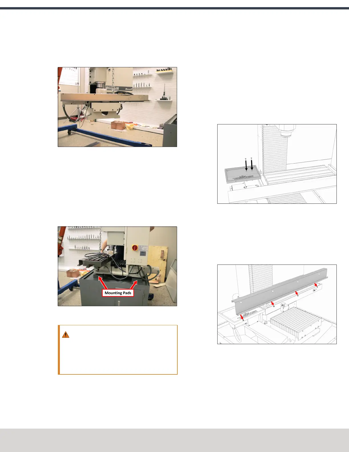
4.7.4 Install the Tool Tray and Drip Guard
1. Find the tool tray that you set aside in "Unpack the
Machine Crate" (page41).
2. Attach the tool tray to the X-axis motor mount with a 4
mm hex wrench and two M6 × 1.0 - 16 flat-head cap
screws.
Figure 4-18: Tool tray aligned to the X-axis motor
mount.
3. Find the drip guard that you set aside in "Unpack the
Machine Crate" (page41).
4. Attach the drip guard to the front of the machine table
with a 3 mm hex wrench and four M5 × 0.8 - 12 socket
head cap screws.
Figure 4-19: Drip guard aligned to the front of the
machine table.
4.7.5 Install the Controller
Depending on your machine configuration, do one of the
following:
l
If You Have a Controller Arm Go to "Install the
Controller Arm" (on the next page).
©Tormach® 2023
Specifications subject to change without notice.
Page 47 Tormach 1100M® Operator's Manual (Version 1223A)
For the most recent version, see tormach.com/support