10: PROGRAMMING
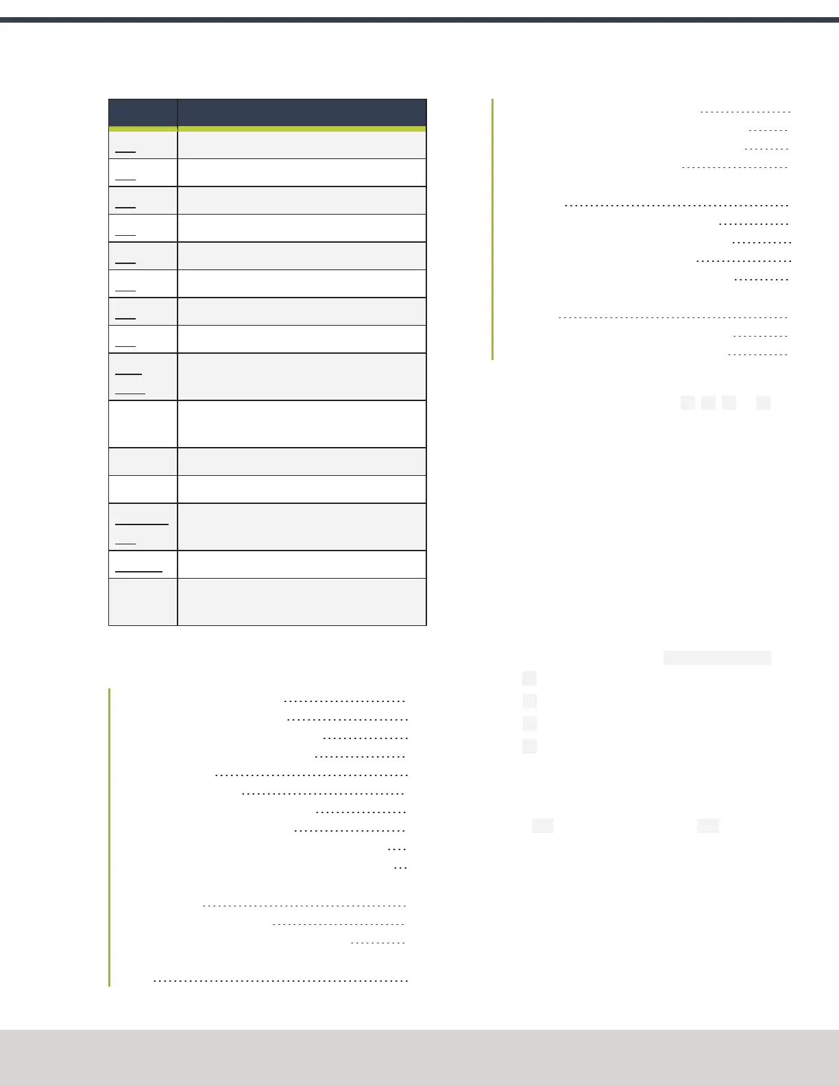
G-Code Description
G80 Cancel canned cycles
G81 Drilling cycle
G82 Simple drilling cycle
G83 Peck drilling cycle
G85 Boring cycle
G86 Boring cycle
G88 Boring cycle
G89 Boring cycle
G90,
G90.1
Arc distance mode
G91,
G91.1
Incremental distance mode
G92 Offset coordinates and set parameters
G92.x Cancel G92, etc.
G93, G94,
G95
Feed rate mode
G96, G97 Spindle control mode
G98 Initial level return / R-point level after canned
cycles
10.2 PROGRAMMING G-CODE
Read the following sections as a G-code reference:
10.2.1 About the Examples Used 199
10.2.2 Rapid Linear Motion (G00) 199
10.2.3 Linear Motion at Feed Rate (G01) 200
10.2.4 Arc at Feed Rate (G02 and G03) 200
10.2.5 Dwell (G04) 202
10.2.6 Set Offsets (G10) 202
10.2.7 Plane Selection (G17, G18, G19) 204
10.2.8 Length Units (G20 and G21) 204
10.2.9 Return to Predefined Position (G28 and G28.1) 204
10.2.10 Return to Predefined Position (G30 and G30.1) 204
10.2.11 Automatically Measure Tool Lengths with an ETS
(G37 and G37.1) 204
10.2.12 Straight Probe (G38.x) 205
10.2.13 Cutter Compensation (G40, G41, G42) 206
10.2.14 Dynamic Cutter Compensation (G41.1 and
G42.1) 207
10.2.15 Apply Tool Length Offset (G43) 207
10.2.16 Engrave Sequential Serial Number (G47) 207
10.2.17 Cancel Tool Length Compensation (G49) 208
10.2.18 Absolute Coordinates (G53) 208
10.2.19 Select Work Offset Coordinate System (G54 to
G54.1 P500) 208
10.2.20 Set Exact Path Control Mode (G61) 208
10.2.21 Set Blended Path Control Mode (G64) 208
10.2.22 Distance Mode (G90 and G91) 208
10.2.23 Arc Distance Mode (G90.1 and G91.1) 209
10.2.24 Temporary Work Offsets (G92, G92.1, G92.2,
and G92.3) 209
10.2.25 Feed Rate Mode (G93, G94, and G95) 209
10.2.26 Spindle Control Mode (G96 and G97) 210
10.2.1 About the Examples Used
Many commands require axis words (X~, Y~ ,Z~, or A~) as an
argument. Unless explicitly stated otherwise, you can make
the following assumptions:
l Axis words specify a destination point
l Axis words relate to the currently active coordinate
system, unless explicitly described as being in the
absolute coordinate system
l Where axis words are optional, any omitted axes retain
their current value
Any items in the command examples not explicitly described
as optional are required.
10.2.2 Rapid Linear Motion (G00)
For rapid linear motion, program: G00 X~ Y~ Z~ A~
l X~ is the X-axis coordinate
l Y~ is the Y-axis coordinate
l Z~ is the Z-axis coordinate
l A~ is the A-axis coordinate
This produces coordinated linear motion to the destination
point at the current traverse rate (or slower, if the machine
won't go that fast). It's expected that cutting won’t take place
when a G00 command is executing. The G00 is optional if the
current motion mode is G00.
Depending on where the tool is located, follow these two basic
rules:
1. If the Z value represents a cutting move in the positive
direction (like out of a hole), the X-axis should be moved
last.
©Tormach® 2023
Specifications subject to change without notice.
Page 199 Tormach 1100M® Operator's Manual (Version 1223A)
For the most recent version, see tormach.com/support
 Loading...


