8. Pull the bracket toward the front of the machine. You'll
make adjustments to the location of the bracket later in
this procedure, but we recommend starting with it
moved forward.
Install the Main Assembly
1. Remove the four preinstalled M8 × 1.25 - 16 mm socket
head cap screws and washers from the bottom of the
ATC electrical cabinet. Then, set all aside for later use.
CAUTION! Team Lift Required:You must have
the aid of more than one person to lift and
move the object. The object is heavy, and lifting
it by yourself can cause serious injury.
2. Lift the ATC main assembly on to the mounting bracket.
Figure 4-81: ATC main assembly positioned above the
mounting bracket.
3. Align the locating pin on the ATC main assembly with
the matching hole in the mounting bracket.
4. Secure the ATC main assembly to the mounting bracket
with the four M8 × 1.25 - 16 mm socket head cap screws
and washers that you set aside in Step 1.
Level the Automatic Tool Changer (ATC)
This section gives instructions to roughly level the ATC on the
machine by using a long, straight rod. More adjustments are
made later in the installation procedure.
NOTICE! After the initial installation, you must level the
ATC. If you don't, there's a risk of machine damage.
Complete the following steps in the order listed:
Prepare the Machine 70
Examine Perpendicularity in the Y Direction 71
Examine Perpendicularity in the X Direction 71
Examine the Alignment of the Carousel Door Opening 71
Prepare the Machine
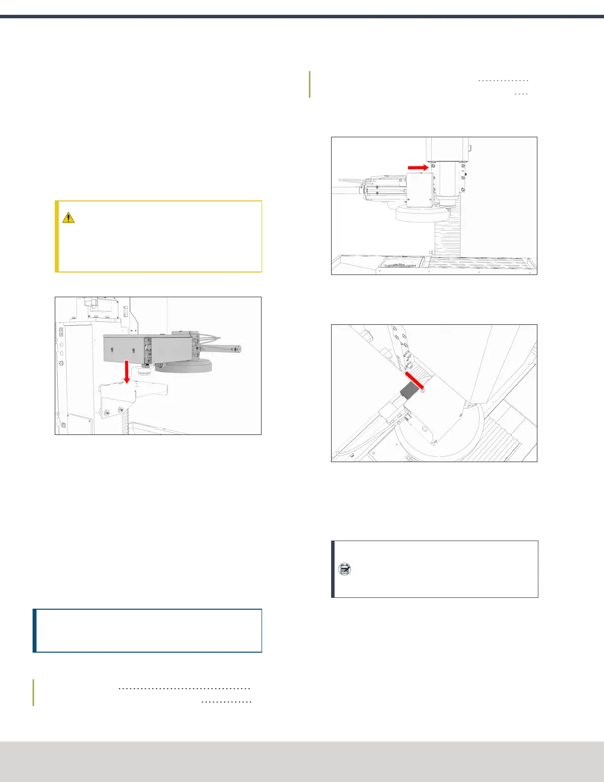
1. Push the tool tray toward the spindle.
Figure 4-82: Tool tray moved in toward the spindle.
2. Verify that the linear bearing on the ATC is flush with the
ATC main assembly.
Figure 4-83: Linear bearing flush with the ATC main
assembly.
3. Find a straight rod between 8 in. and 12 in. (203 mm and
305 mm) long. Verify that it's straight: roll it on a known
flat surface (like a granite surface plate).
Note: You'll use the rod to verify that the ATC is
correctly installed on the mill, so it must be
straight.
4. Put the alignment rod into a tool holder.
©Tormach® 2023
Specifications subject to change without notice.
Page 70 Tormach 1100M® Operator's Manual (Version 1223A)
For the most recent version, see tormach.com/support
4: INSTALLATION