4: INSTALLATION
3. Dependingon whether the tool holder releases or not, do
one of the following:
l
If the Tool Holder Releases Tighten the Power
Drawbar in quarter-turn increments with two
adjustable wrenches. After each turn, push the
Release Tool button. Stop when the tool holder does
not release. Then, loosen the Power Drawbar one
quarter-turn with two adjustable wrenches.
l
If the Tool Holder Doesn't Release Loosen the
Power Drawbar in quarter-turn increments with two
adjustable wrenches while pushing the Release Tool
button. Stop when the tool holder releases.
4. Make a visual reference to help you set or adjust the
drawbar tension in the future: use a paint pen to make a
witness mark on both the head of the drawbar and the
end of the spindle.
About Drawbar Tension
While machining, the Tormach Tooling System (TTS) collet
holds a Tormach Tooling System (TTS) tool holder in the
spindle by applying a clamping force to both the shank and the
shoulder of the tool. The tension force that is applied to the
drawbar pulls the Tormach Tooling System (TTS) collet into the
spindle taper, which then applies the clamping force to the
Tormach Tooling System (TTS) tool.
The force on the drawbar — known as drawbar tension — is
applied differently depending on the tool changing method:
l
Automatic (using the Power Drawbar) Tension is
applied by the compressed spring washers.
l
Manual Tension is applied when you tighten the
drawbar into the collet using a wrench.
Adjust the Initial Setup
In this adjustment, you'll verify that there's enough clearance
between the end of the drawbar and the Power Drawbar
cylinder.
NOTICE! If you don't do this adjustment, there's a risk
that the drawbar can loosen, or that operations can be
louder than normal.
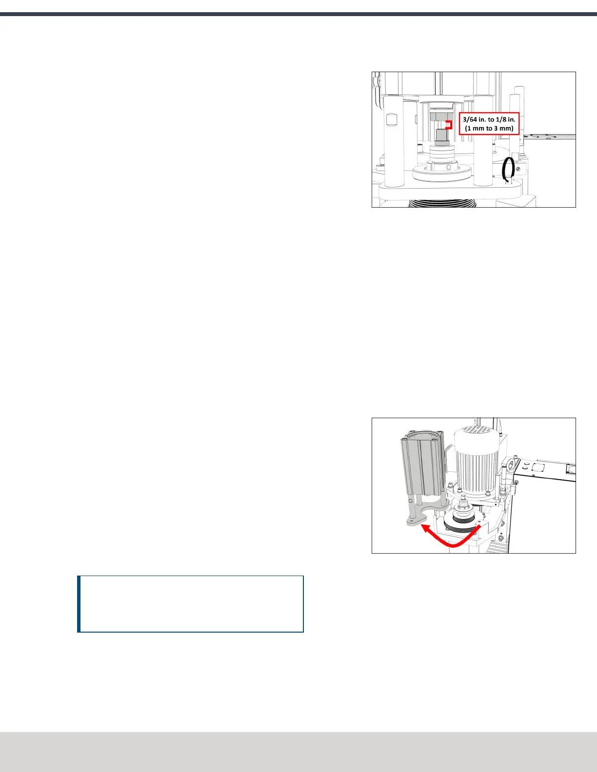
1. Examine the space between the hex head screw on the
Power Drawbar cylinder's rod and the top of the
drawbar.
Figure 4-93: Correctly spaced drawbar and Power
Drawbar cylinder.
2. Verify that the gap is between 3/64 in. and 1/8 in. (1
mm and 3 mm). Depending on the size of the gap, do
one of the following:
l
Between 3/64 in. and 1/8 in. (1 mm and 3 mm)
You have completed adjusting the initial setup. Go to
Operation.
l
Less Than 3/64 in. (1 mm) Go to Step 3.
3. Disconnect the shop's air supply from the Power
Drawbar button.
4. Pull out the quick-release pin.
5. Pivot the Power Drawbar cylinder assembly to the left so
that you can access the Power Drawbar cylinder's rod.
Figure 4-94: Power Drawbar cylinder pivoted to the
left.
©Tormach® 2023
Specifications subject to change without notice.
Page 75 Tormach 1100M® Operator's Manual (Version 1223A)
For the most recent version, see tormach.com/support