4: INSTALLATION
3. Remove the coolant hose bracket from the rear of the
Machine Stand. Set the hardware aside.
Figure 4-75: Coolant hose bracket and its hardware
removed from the Machine Stand.
4. Attach the provided Y-fitting to the coolant hose bracket,
and then install the coolant hose bracket back on the
Machine Stand using the hardware that you set aside in
Step 4.
5. Identify the two provided coolant hoses: the self-
retracting coolant hose and the long coolant hose.
6. Put the self-retracting coolant hose into the top of the Y-
fitting.
7. Put the provided plug into the remaining side of the Y-
fitting.
8. Cut a 3 in. (76 mm) piece of the longer coolant hose with
snips.
9. Put the newly cut piece of the coolant hose into the
bottom of the Y-fitting. Then, put the provided elbow
onto the its loose end.
10. Put the remainder of the long coolant hose into the open
end of the elbow.
11. Route the loose end of the long coolant hose through the
Machine Stand, through the energy chain, and to the
spindle head.
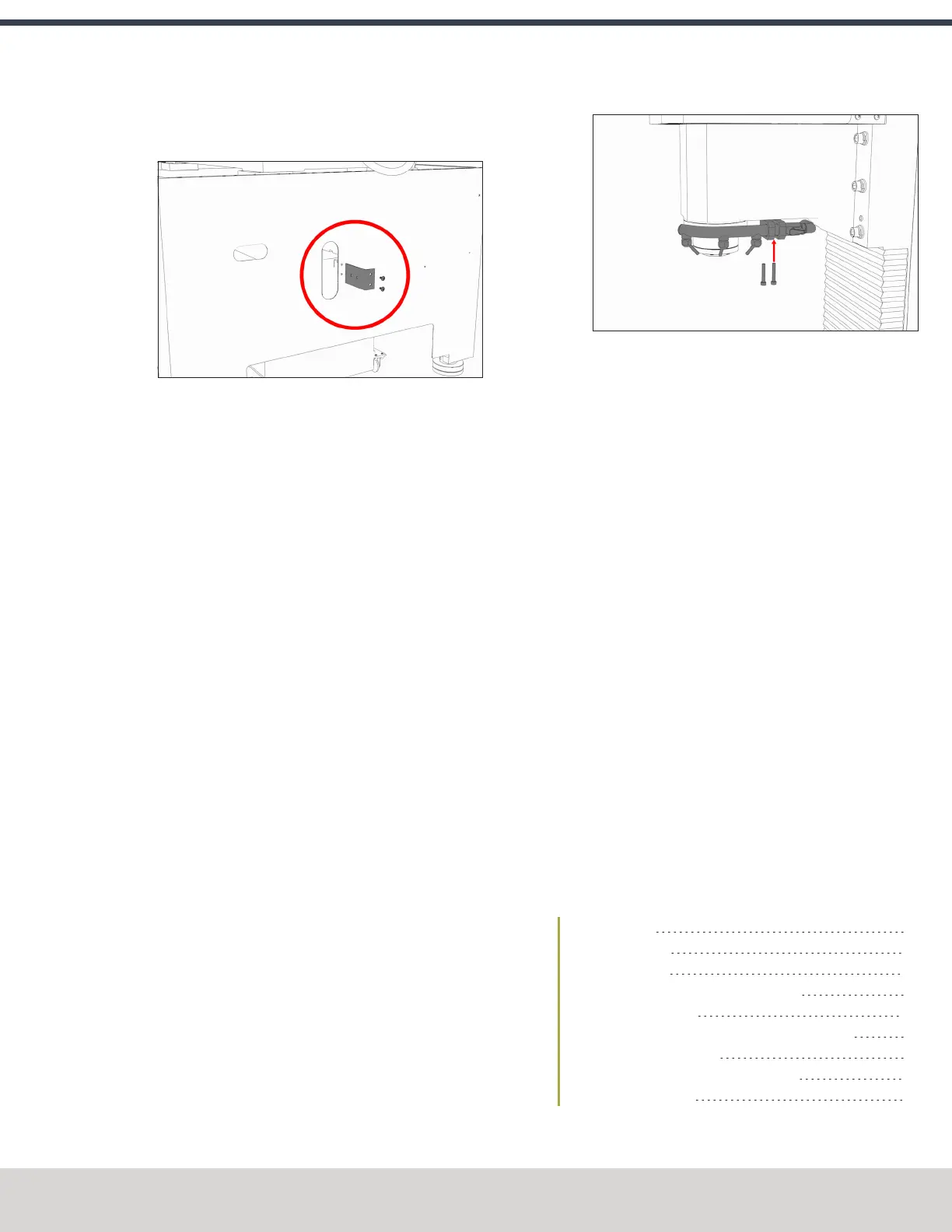
12. Attach the coolant manifold to the spindle nose with the
two screws provided.
Figure 4-76: Attaching the coolant manifold to the
spindle nose.
13. Put the loose end of the long coolant hose into the
coolant manifold.
14. Route the loose end of the self-retracting coolant hose
through the rear of the Machine Stand, and then put it
into the elbow on the coolant pump.
15. Move the coolant tank into the Machine Stand.
16. Route the power cord on the coolant pump to the rear of
the electrical cabinet, and connect it to the Coolant
PumpPower outlet.
17. Verify that the coolant setup operates properly:
a. From the PathPilot interface, on the Main tab, select
Coolant.
The coolant pump powers on.
b. Select Coolant again.
The coolant pump powers off.
18. Secure coolant tank’s front panel to the Machine Stand
with the two provided M8 × 1.25 – 16 flanged button
head cap screws. Adjust the front panel alignment as
necessary using the six mounting screws securing the
front panel to the coolant tank.
4.8.4 Install the Automatic Tool Changer (ATC)
Complete the following steps in the order listed:
Required Tools 68
Air Requirements 68
Before You Begin 68
Disassemble the Power Drawbar Button 68
Install the Air Cylinder 69
Mount the Automatic Tool Changer (ATC) Bracket 69
Install the Main Assembly 70
Level the Automatic Tool Changer (ATC) 70
Make Air Connections 73
©Tormach® 2023
Specifications subject to change without notice.
Page 67 Tormach 1100M® Operator's Manual (Version 1223A)
For the most recent version, see tormach.com/support