4: INSTALLATION
9. Remove the spindle lock arm on the spindle door.
Figure 4-49: Spindle lock arm on the spindle door.
Assemble the Power Drawbar
1. Find the drawbar that you set aside in "Disassemble the
Original Drawbar" (on the previous page).
2. Remove the drawbar bushing from the drawbar, and set
it aside.
3. Put Anti-Seize (provided) on the bottom of the drawbar
head.
4. Find the eight spring washers provided.
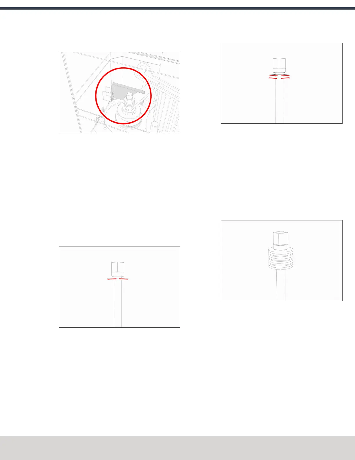
5. Move one spring washer on the drawbar, with the
convex side of the spring washer toward the drawbar
head.
Figure 4-50: Convex side of the spring washer toward
the drawbar head.
6. Move another spring washer on the drawbar, with the
concave side of the spring washer toward the concave
side of the spring washer from Step 5.
Figure 4-51: Concave sides of two spring washers
together.
7. Put Anti-Seize on the edge of the contact surface
between the pair of spring washers that you put on the
drawbar in Steps 5 and 6.
8. Repeat Steps 5 through 7 for the remaining six spring
washers. Make sure that you put Anti-Seize on the spring
washers at every contact point.
9. Examine the stack of spring washers. Make sure that all
eight spring washers are on the drawbar and arranged in
four sets of opposing pairs.
Figure 4-52: All eight spring washers on the drawbar.
10. Find the drawbar bushing that you set aside in Step 2,
and put it on the drawbar. Make sure that the smaller
diameter of the drawbar bushing is toward the bottom
of the drawbar.
11. Put Anti-Seize on the top of the drawbar bushing.
©Tormach® 2023
Specifications subject to change without notice.
Page 59 Tormach 1100M® Operator's Manual (Version 1223A)
For the most recent version, see tormach.com/support