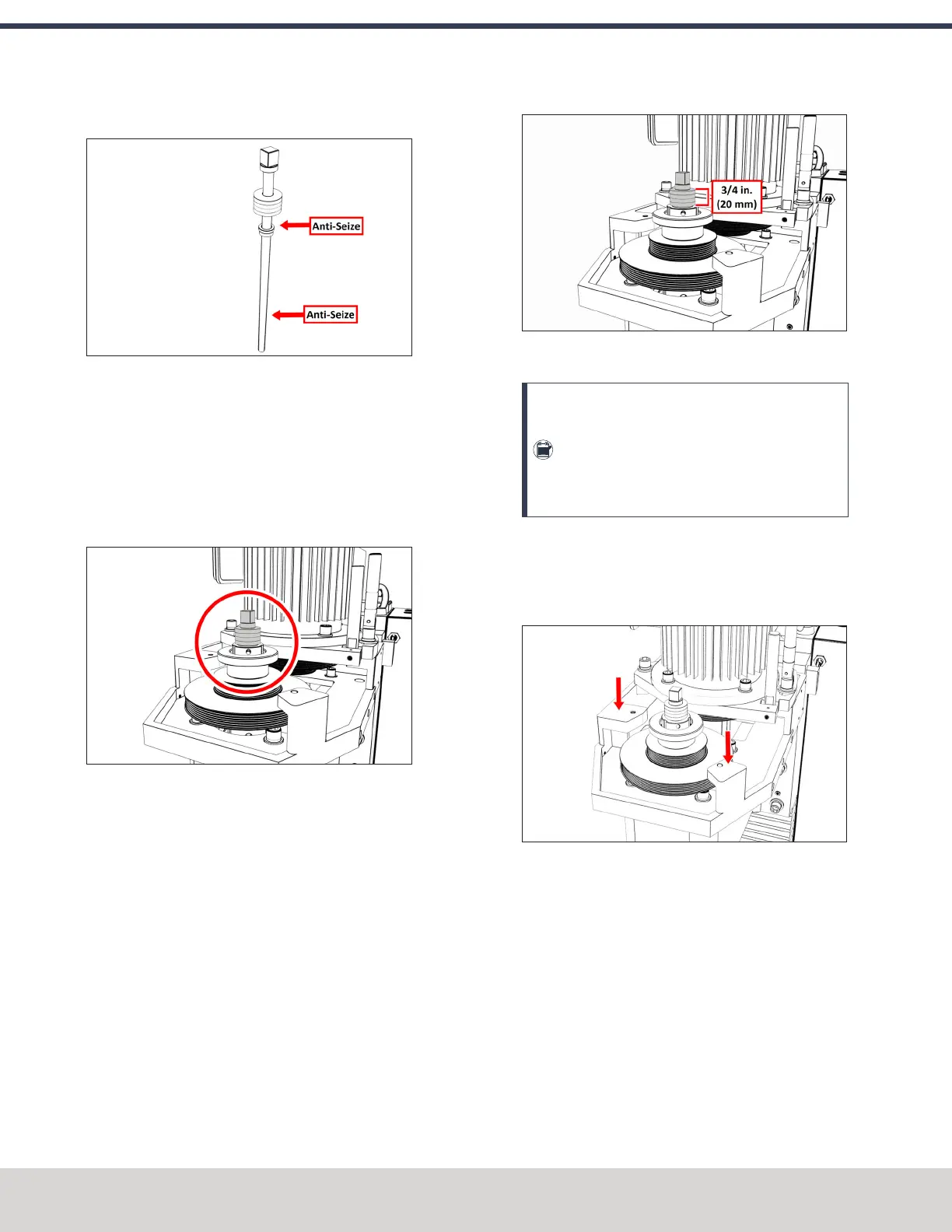
12. Put Anti-Seize on the bottom threads of the drawbar.
Figure 4-53: Locations to apply Anti-Seize on the
drawbar assembly.
13. Put Anti-Seize on the outside taper of the Tormach
Tooling System (TTS) collet. Make sure that there is no
Anti-Seize on the inside of the collet.
14. Put the drawbar assembly into the spindle.
15. While using one hand to insert the collet into the
spindle, use the other to turn the drawbar into the collet.
Figure 4-54: Drawbar assembly installed in the
spindle motor cabinet.
16. Hand-tighten the drawbar.
17. While using one hand to insert an empty Tormach
Tooling System (TTS) tool holder into the collet, use the
other to tighten the collet into the drawbar with an
adjustable wrench.
18. Use two large, adjustable wrenches to tighten the Power
Drawbar until the spring washer stack is compressed to
a height of 3/4 in. (20 mm).
Figure 4-55: Correctly compressed spring washer
stack.
Note: Later in this procedure, after you
complete the initial installation, you'll do a final
drawbar tension adjustment. For more
information, see "Adjust the Drawbar Tension"
(page74).
19. Find the Power Drawbar cylinder assembly provided.
20. Identify the Power Drawbar mounting surfaces inside of
the spindle motor cabinet, as shown in the following
image.
Figure 4-56: Power Drawbar mounting surfaces inside
of the spindle motor cabinet.
21. Put the Power Drawbar cylinder assembly on the
mounting surface.
22. Find the 10 mm shoulder screw provided, and then put
Anti-Seize on its threads.
©Tormach® 2023
Specifications subject to change without notice.
Page 60 Tormach 1100M® Operator's Manual (Version 1223A)
For the most recent version, see tormach.com/support
4: INSTALLATION
 Loading...


