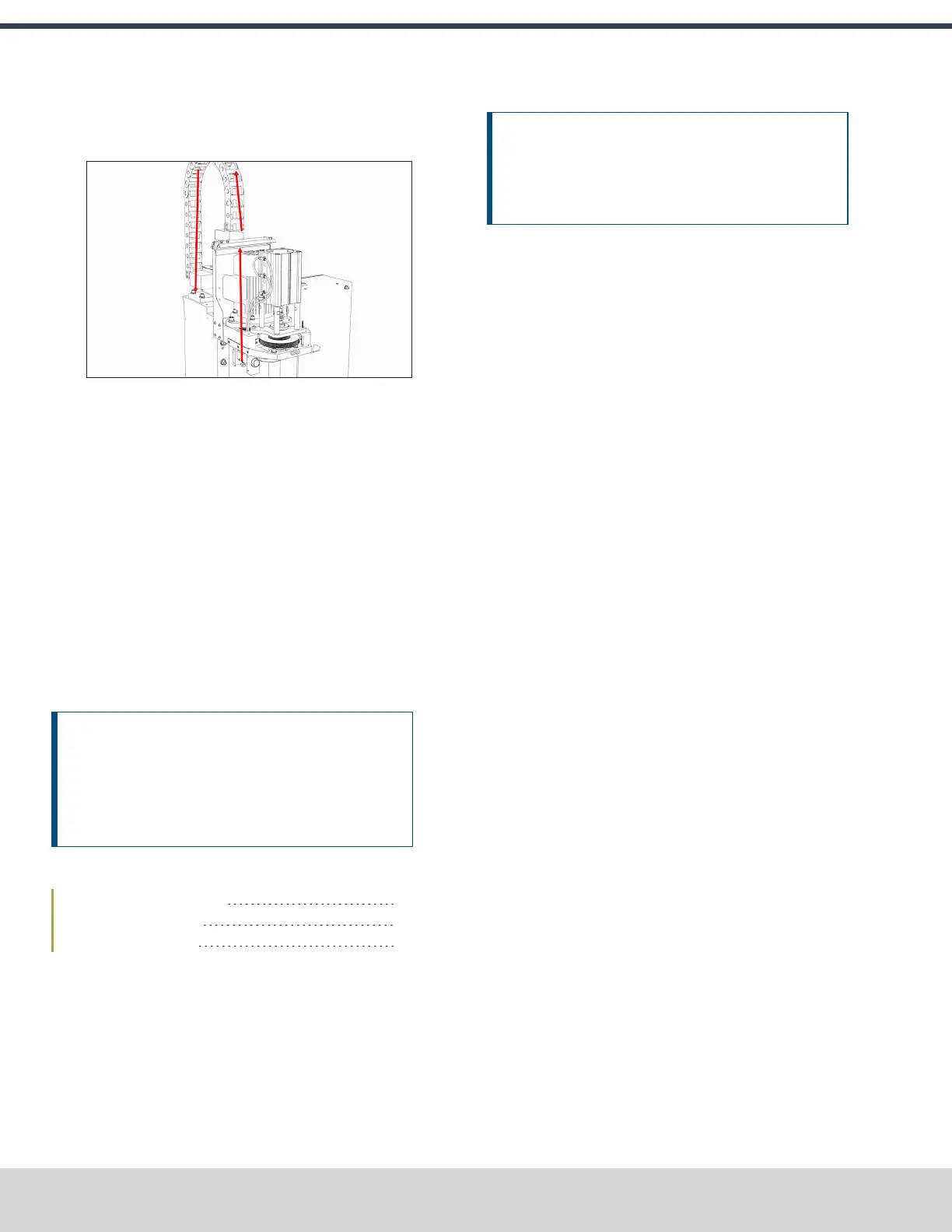
11. Route the loose end of the 1/4 in. plastic tube through
the energy chain and toward the FRL
Figure 4-67: Air line routing through the energy chain.
12. Connect the 1/4 in. plastic tube to the Output port on the
FRL.
13. Find the 1/4 in. plastic tube provided. Then, connect one
end to the Input port on the FRL.
14. Put the 1/4 in. push-connect air fitting adapter on the
loose end of the 1/4 in. plastic tube.
15. Route the 1/4 in. plastic tube to your shop's air supply
and connect it with the adapter.
16. Replace the button box cover with a 3 mm hex wrench
and the screws that you set aside in Step 2.
Adjust the Power Drawbar
After installing the Power Drawbar, you must adjust it.
NOTICE! After the initial installation, you must complete
a final drawbar tension adjustment. For more
information, see "Adjust the Drawbar Tension" (page74).
If you don't complete a drawbar tension adjustment,
there's a risk of tool pull-out.
Complete the following steps in the order listed:
Adjust the Drawbar Tension 64
About Drawbar Tension 64
Adjust the Initial Setup 65
Adjust the Drawbar Tension
This adjustment sets the highest possible drawbar tension
while still allowing the Power Drawbar cylinder to release the
tool. For information, see"About Drawbar Tension" (page75).
NOTICE! After the initial installation, you must examine
the drawbar tension weekly. During periods of heavy use,
examine the drawbar tension more frequently. If you
don't, there's a risk of tool pull-out.
To adjust the drawbar tension:
1. Put an empty Tormach Tooling System (TTS) tool holder
into the collet.
2. While using one hand to support the tool holder, use the
other to push the Release Tool button.
3. Dependingon whether the tool holder releases or not, do
one of the following:
l
If the Tool Holder Releases Tighten the Power
Drawbar in quarter-turn increments with two
adjustable wrenches. After each turn, push the
Release Tool button. Stop when the tool holder does
not release. Then, loosen the Power Drawbar one
quarter-turn with two adjustable wrenches.
l
If the Tool Holder Doesn't Release Loosen the
Power Drawbar in quarter-turn increments with two
adjustable wrenches while pushing the Release Tool
button. Stop when the tool holder releases.
4. Make a visual reference to help you set or adjust the
drawbar tension in the future: use a paint pen to make a
witness mark on both the head of the drawbar and the
end of the spindle.
About Drawbar Tension
While machining, the Tormach Tooling System (TTS) collet
holds a Tormach Tooling System (TTS) tool holder in the
spindle by applying a clamping force to both the shank and the
shoulder of the tool. The tension force that is applied to the
drawbar pulls the Tormach Tooling System (TTS) collet into the
spindle taper, which then applies the clamping force to the
Tormach Tooling System (TTS) tool.
The force on the drawbar — known as drawbar tension — is
applied differently depending on the tool changing method:
l
Automatic (using the Power Drawbar) Tension is
applied by the compressed spring washers.
l
Manual Tension is applied when you tighten the
drawbar into the collet using a wrench.
©Tormach® 2023
Specifications subject to change without notice.
Page 64 Tormach 1100M® Operator's Manual (Version 1223A)
For the most recent version, see tormach.com/support
4: INSTALLATION