4: INSTALLATION
c.
Right Side (Using 6" Through-Bolts into T-Slots)
X work envelope is reduced in this configuration, but
it provides clearance for long tooling in the ATC.
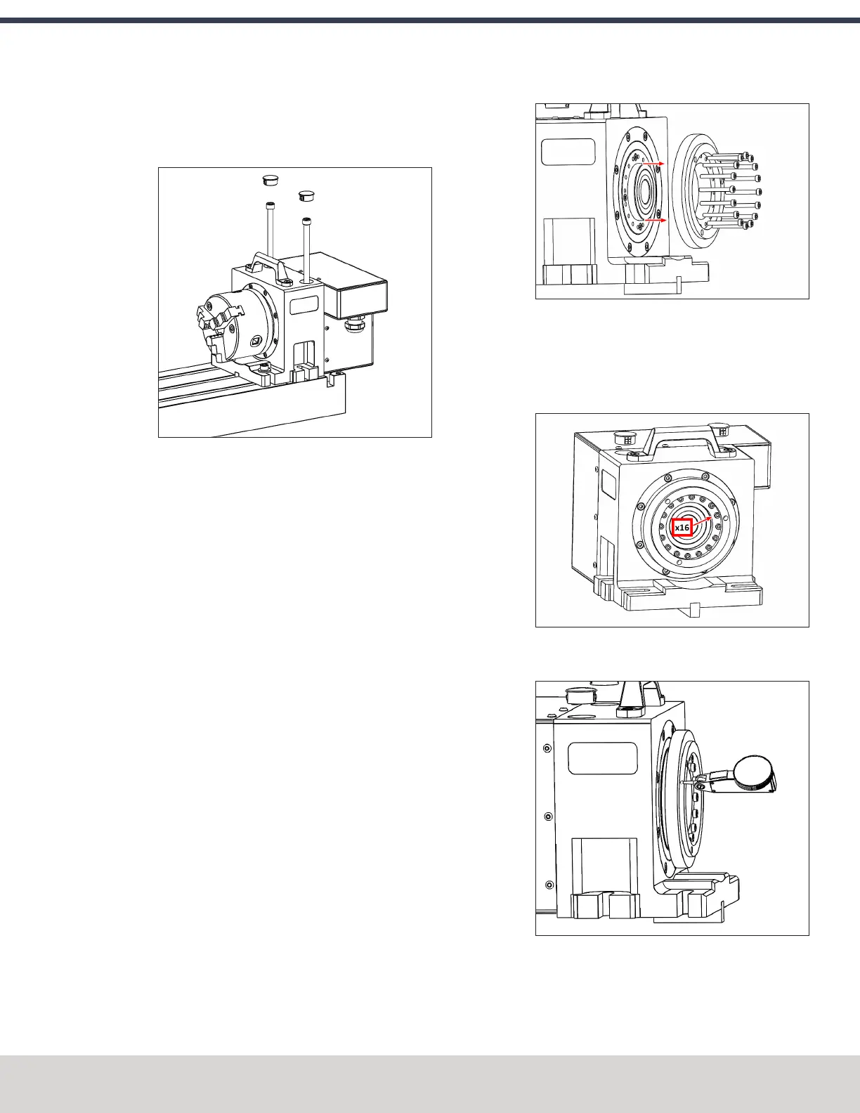
2. Feed the motor cable under the electrical cabinet and
plug it into the 7-pin connector you installed with the
driver kit.
3. Loosely install the 5/16" mounting bolts, using either the
threaded accessory mounting holes on your machine
table or T-nuts.
4. Use the key on the bottom of the 4th axis to perform a
rough alignment of the unit to the T-slots in your
machine's table. If you need to perform a precise
alignment, put a straight test bar into the chuck and
sweep along it in X with an indicator. Adjust the
orientation of the 4th axis until the reading does not
deviate during the sweep.
5. Tighten the mounting hardware with a hex wrench.
Center the Chuck Mounting Plate
1. Remove the chuck from the 4th axis, if installed.
2. From the PathPilot interface, verify that you can rotate
the 4th axis with either the jog keys on the keyboard or
the jog shuttle.
3. The mounting plate is designed for a loose fit onto the
output of the harmonic drive. This allows you to adjust
the center of rotation to control runout at the chuck.
4. Slightly loosen the 16 M3 button head cap screws that
hold the chuck mounting plate to the output of the
harmonic drive. They should still be snug enough that the
mounting plate is held in place by friction but can be
nudged with a dead-blow hammer.
5. Put a the tip of a dial test indicator on the mounting
flange for the chuck.
6. Using PathPilot, jog the 4th axis 360 degrees, noting the
spot where the indicator is highest.
©Tormach® 2023
Specifications subject to change without notice.
Page 83 Tormach 1100M® Operator's Manual (Version 1223A)
For the most recent version, see tormach.com/support