4: INSTALLATION
Adjust the Initial Setup
In this adjustment, you'll verify that there's enough clearance
between the end of the drawbar and the Power Drawbar
cylinder.
NOTICE! If you don't do this adjustment, there's a risk
that the drawbar can loosen, or that operations can be
louder than normal.
1. Examine the space between the hex head screw on the
Power Drawbar cylinder's rod and the top of the
drawbar.
Figure 4-68: Correctly spaced drawbar and Power
Drawbar cylinder.
2. Verify that the gap is between 3/64 in. and 1/8 in. (1
mm and 3 mm). Depending on the size of the gap, do
one of the following:
l
Between 3/64 in. and 1/8 in. (1 mm and 3 mm)
You have completed adjusting the initial setup. Go to
Operation.
l
Less Than 3/64 in. (1 mm) Go to Step 3.
3. Disconnect the shop's air supply from the Power
Drawbar button.
4. Pull out the quick-release pin.
5. Pivot the Power Drawbar cylinder assembly to the left so
that you can access the Power Drawbar cylinder's rod.
Figure 4-69: Power Drawbar cylinder pivoted to the
left.
6. Remove the hex head screw on the Power Drawbar
cylinder’s rod with an adjustable wrench, and set it
aside.
Figure 4-70: Hex head screw on the Power Drawbar
cylinder's rod.
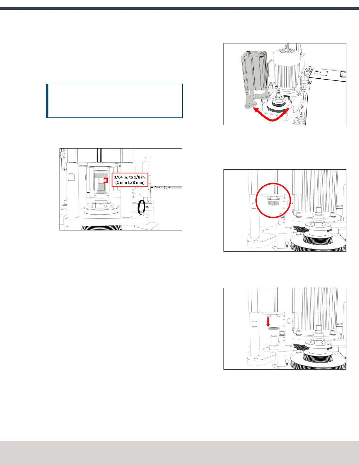
7. Remove the M16 washer from the Power Drawbar
cylinder’s rod, and set it aside.
Figure 4-71: M16 washer removed from the Power
Drawbar cylinder's rod.
8. Put the hex head screw back in, and then tighten it
completely with an adjustable wrench.
9. Pivot the Power Drawbar cylinder to the original location.
10. Push in the quick-release pin.
©Tormach® 2023
Specifications subject to change without notice.
Page 65 Tormach 1100M® Operator's Manual (Version 1223A)
For the most recent version, see tormach.com/support