5.1 SYSTEM REFERENCE
To operate your machine, you must become familiar with the
components of its system.
5.1.1 Machine Table
The machine table is 34" × 9.5" (864 mm × 241 mm).
Don't put more than 500 lb (227 kg) on the machine table.
Always verify that the workpiece and workholding devices are
centered on the machine table.
The machine table has three T-slots along the X-axis, used to
secure workholding devices (on which to secure your workpiece
while machining):
l
T-Slots 5/8" (15.9 mm) (three slots)
l
T-Slot Spacing 2-3/8" (60.3 mm)
l
Center T-SlotPrecision ground to 0.625" (15.9 mm)
5.1.2 Spindle
The machine spindle uses an R8 taper to hold Tormach Tooling
System (TTS) tool holders.
l
Spindle Power 2 hp (1.5 kW)
About the Spindle
The machine spindle gives power to the cutting tool, which
allows it to remove material from the workpiece. The spindle
is driven by the spindle motor.
Operate the spindle either manually or by G-code commands
(entered in the MDI Line DROfield or programmed into a G-
code program). Manually controlling the spindle is useful when
you're setting work offsets for tools that require the spindle to
be running (like “wiggler”-style edgefinders or coaxial
indicators).
The machine's spindle rotates either clockwise (forward) or
counterclockwise (reverse) at a specified spindle speed.
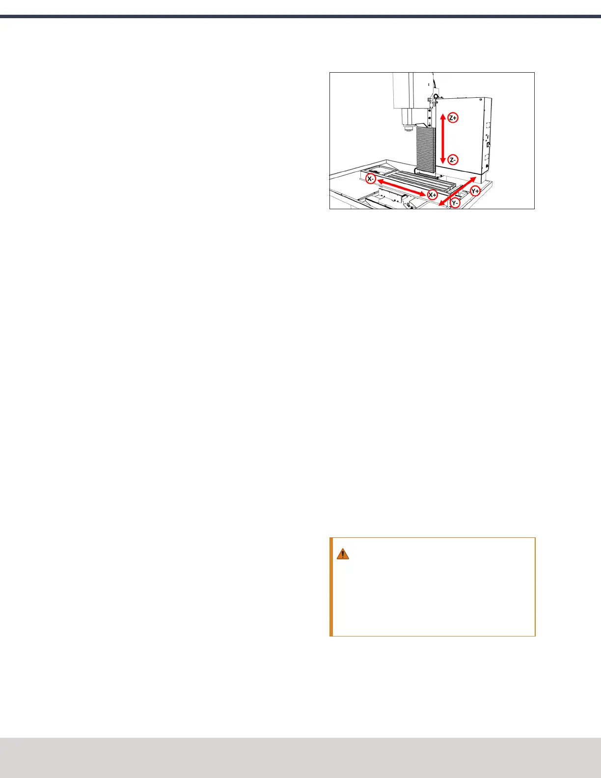
5.1.3 Axes
The machine has three linear axes of motion, and one optional
rotary axis, used for machining:
l The X-axis, which is (horizontally) along the long side of
the machine table.
l The Y-axis, which is (horizontally) along the short side of
the machine table.
l The Z-axis, which is (vertically) along the mill column.
l (Optional) The A-axis, which is the axis of rotation that is
typically aligned to the X-axis.
Figure 5-1: Axis directions on the machine.
Each axis has a different limit of travel, which is the distance it
moves before reaching a limit switch:
l
X-Axis 18"(457 mm)
l
Y-Axis 11" (279 mm)
l
Z-Axis 16.25" (413 mm)
5.2 BASIC CONTROLS REFERENCE
To safely and effectively operate your machine, you must
become familiar with how it moves. The machine has two
forms of basic controls:machine controls and the PathPilot
interface.
5.2.1 Machine Controls
The following controls energize the machine's control
electronics:
l The Main Disconnect switch, located on the right side of
the electrical cabinet.
The Main Disconnect switch has two positions: OFF and
ON. When it's in the OFF position, it separates the other
machine control electronics from the mains electrical
supply. When it's in the ON position, the other machine
control electronics are able to receive power.
WARNING! Before opening the electrical
cabinet for maintenance or troubleshooting,
you must lockout the mains power: Turn the
Main Disconnect switch to the OFF position,
and secure an approved lockout device through
the lockout rings at the bottom of the switch.
©Tormach® 2023
Specifications subject to change without notice.
Page 112 Tormach 1100M® Operator's Manual (Version 1223A)
For the most recent version, see tormach.com/support
5: SYSTEM BASICS