8: BASIC OPERATIONS
other tool lengths. Use any surface that is parallel (within 0.02
mm) to the machine table. For example:
l A 1-2-3 Block Set (PN 31950)
l Box parallel
There are two steps to touch off the tool offsets. Complete the
following steps in the order listed:
Set a Known Reference Height 181
Measure Tools Using a Known Reference Height 181
Set a Known Reference Height
This procedure sets a new Z zero position for the currently
selected work offset.
To set a known reference height:
1. Identify a precision surface to use as a reference surface
(like a 1-2-3 Block Set), and put it below the spindle on
the machine table. Verify that there's a clear path from
the spindle to the machine table.
2. Verify that the drive dogs won't contact the reference
surface before the end face of the spindle.
3. Set a new, unused work offset (like G55).From the
PathPilot interface, on the Main tab, in the MDI Line
DROfield, type a work offset. Then select the Enter key.
For information, see "Set Work Offsets" (on the next
page).
4. If there's already a tool in the spindle, remove it.
5. From the PathPilot interface, in the Tool DROfield, type
0. Then select the Enter key.
6. Slowly jog the Z-axis down (-Z) until it's 0.04 in. (1 mm)
from the reference surface.
7. Measure the thickness of a piece of paper, and put the
paper on the reference surface. Note the thickness of the
paper for later.
8. While moving the paper back-and-forth across the
reference surface, slowly step the Z-axis down (-Z) until
you feel a light pull on the piece of paper. This indicates
that the paper is contacting the end face of the spindle.
Note: It's easier to use step jogging for this
task. For information on step jogging, see
"About Step Jogging" (page177).
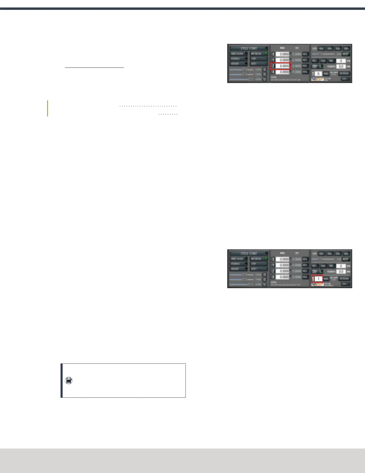
9. From the PathPilot interface, in the Z-axis work offset
DROfield, type the thickness of the piece of paper. Then
select the Enter key.
Figure 8-9: Z-axis work offset DRO field.
The reference surface is now set as the Z zero position in
the current coordinate system.
10. To set the tool length offset, go to "Measure Tools Using
a Known Reference Height" (page189).
Measure Tools Using a Known Reference Height
This procedure sets the tool length offset using a known
reference height. If you have not yet done so, you must first set
the Z zero position; go to Set a Known Reference Height.
To measure tools using a known reference height:
1. Verify that the reference surface is still on the machine
table with the piece of paper.
2. From the PathPilot interface, on the Offsets tab, find an
unused tool number in the Tool Table window. Then,
type a description for the tool you're measuring.
3. Put the tool holder into the spindle.
4. From the PathPilot interface, in the Tool DROfield, type
the number of the tool.Then select the Enter key.
Figure 8-10: Tool DROfield.
5. Slowly jog the Z-axis down (-Z) until it is 0.04 in. (1 mm)
from the reference surface.
6. Continue to slowly jog the Z-axis while slowly moving
the piece of paper back-and-forth on the reference
surface.
7. Stop jogging the Z-axis when you feel a light pull on the
piece of paper, which indicates that it is in contact with
the tool.
8. From the PathPilot interface, on the Offsets tab, in the
Tool Table, select the tool for which you previously wrote
a description.
©Tormach® 2023
Specifications subject to change without notice.
Page 181 Tormach 1100M® Operator's Manual (Version 1223A)
For the most recent version, see tormach.com/support

 Loading...

