4: INSTALLATION
3. Install the button box base, standoffs, and button
assembly on the mill head with two M4 × 0.7 - 50 socket
head cap screws.
Figure 4-63: Button box base installed on the mill
head.
4. Remove and discard the shipping plugs on the Power
Drawbar.
5. Find the Retract (white) air line provided. Then, connect
one end to the Retract port on the Power Drawbar
button.
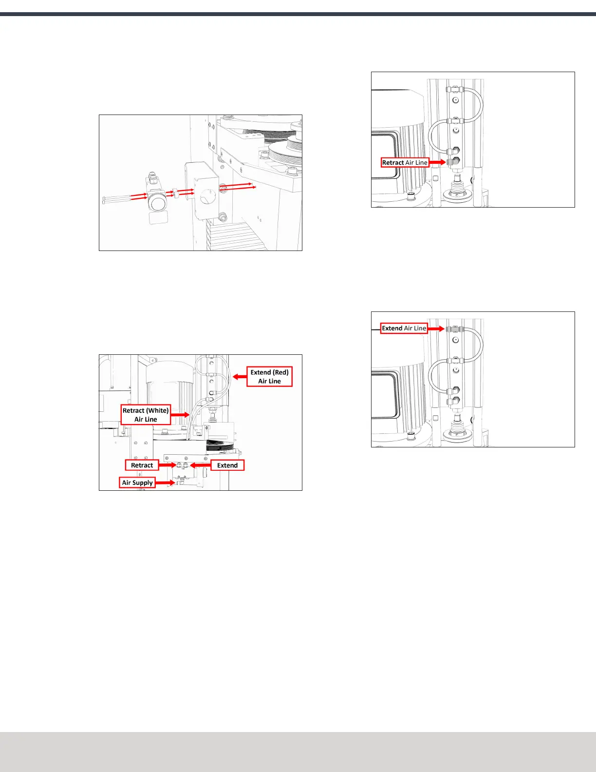
Figure 4-64: Power Drawbar air line routing.
6. Route the loose end of the Retract air line to the Power
Drawbar cylinder, and then connect it to the lowest
elbow fitting.
Figure 4-65: Retract fitting on the Power Drawbar
cylinder.
7. Find the Extend (red) air line provided. Then, connect one
end to the Extend port on the Power Drawbar button.
8. Route the loose end of the Extend air line to the Power
Drawbar cylinder, and then connect it to the top tee
fitting.
Figure 4-66: Extend fitting on the Power Drawbar
cylinder.
9. Use the three cable ties to secure both air lines together.
10. Find the 1/4 in. plastic tube provided. Then, connect one
end to the Air Supply push-to-connect elbow on the
Power Drawbar button.
©Tormach® 2023
Specifications subject to change without notice.
Page 63 Tormach 1100M® Operator's Manual (Version 1223A)
For the most recent version, see tormach.com/support