2. Power on the machine and the PathPilot controller.
a. Turn the Main Disconnect switch to ONon the side of
the electrical cabinet.
b. Twist out the machine's red Emergency Stop button,
which enables movement to the machine axes and
the spindle.
c. Press the Reset button.
d. Bring the machine out of reset and reference it.
3. Verify that the ATC is all the way forward (toward the
spindle), and then slowly move the Z-axis down (-Z) to
examine the clearance of the carousel door opening.
4. Verify that the carousel door opening is approximately
equal to the front back and left of the spindle mounting
flange:
l If the carousel door opening is approximately equal,
go to Step 8.
Figure 4-87: Distance between the carousel door
opening and the spindle mounting flange.
l If the carousel door opening must be adjusted, go to
Step 5.
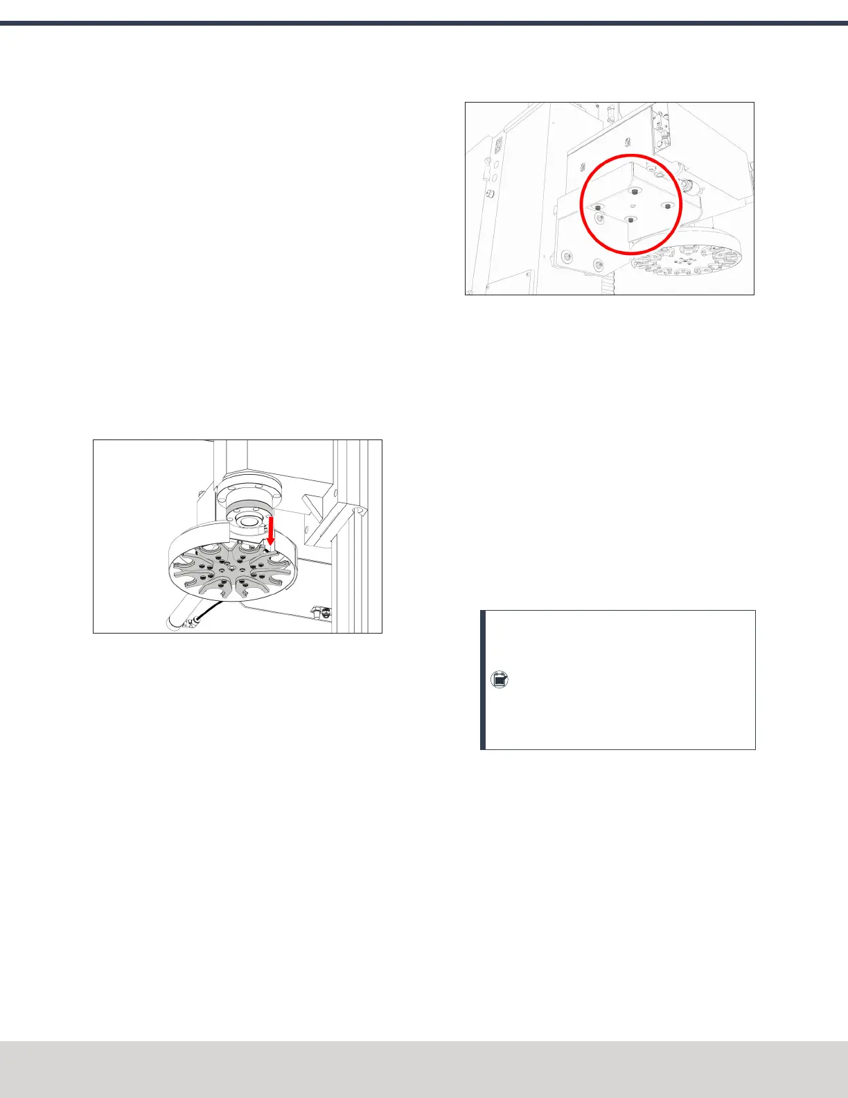
5. Loosen the four socket head cap screws that secure the
ATC main assembly to the mounting bracket with a 6
mm hex wrench.
Figure 4-88: Socket head cap screws securing the ATC
main assembly to the mounting bracket.
6. Adjust the carousel door opening as required:
l
If the Carousel Door Opening is Contacting the
Front Pivot the ATC around the locating pin on the
bottom of the mounting bracket toward the front of
the machine (closer to you).
l
If the Carousel Door Opening is Contacting the
Back Pivot the ATC around the locating pin on the
bottom of the mounting bracket toward the back of
the machine (closer to the machine column).
l
If the Carousel Door Opening is Contacting the
Left Loosen the four flange nuts that attach the
mounting bracket to the column to move the bracket
forward or backward.
Note: Moving the ATC mounting bracket
could change the position of the tilt standoff
(on the Z-column). If you move it, you must
verify that the ATC is still correctly installed;
go to "Examine Perpendicularity in the Y
Direction" (on the previous page).
Repeat this step as needed.
7. Tighten the socket head cap screws and the flange nuts
(if you loosened them in Step 5).
8. Move the tool tray to its retracted position.
9. Center the machine table: from the PathPilot interface,
in the MDILine DRO field, type G20 G53 G1 X9 Y-
5.5 Z0 F20. Then select the Enter key.
©Tormach® 2023
Specifications subject to change without notice.
Page 72 Tormach 1100M® Operator's Manual (Version 1223A)
For the most recent version, see tormach.com/support
4: INSTALLATION