CHAPTER 3 INTERFACE
B-EP Series
3-50
(1) Connector pin diagram and signal description
Pin No. Signal name Function Signal direction
1
2
SG Ground line for all data and control signals.
(without the noise filter)
–
3 RXD Line for data which the host sends to the printer.
Logic “1” is a “Low” level, while logic “0” is a “High”
level.
It is in a “Low (Mark)” state when no transmission is in
progress.
In power save mode, it should be in a “Low (Mark)”
state. If it is in a “High” state, the printer cannot be
returned to the normal state from the power save
mode by opening/closing the cover, or pressing the
[POWER] switch or the [FEED] switch.
← Host
4 TXD Line for data which the printer sends to the host.
Logic “1” is a “Low” level, while logic “0” is a “High”
level. It is in a “Low (Mark)” state when no
transmission is in progress. It is in a high impedance
state in power save mode.
Printer →
5 CTS N/A
–
6 RTS N/A
–
7 TEST The signal is connected with SG.
–
8 N.C
–
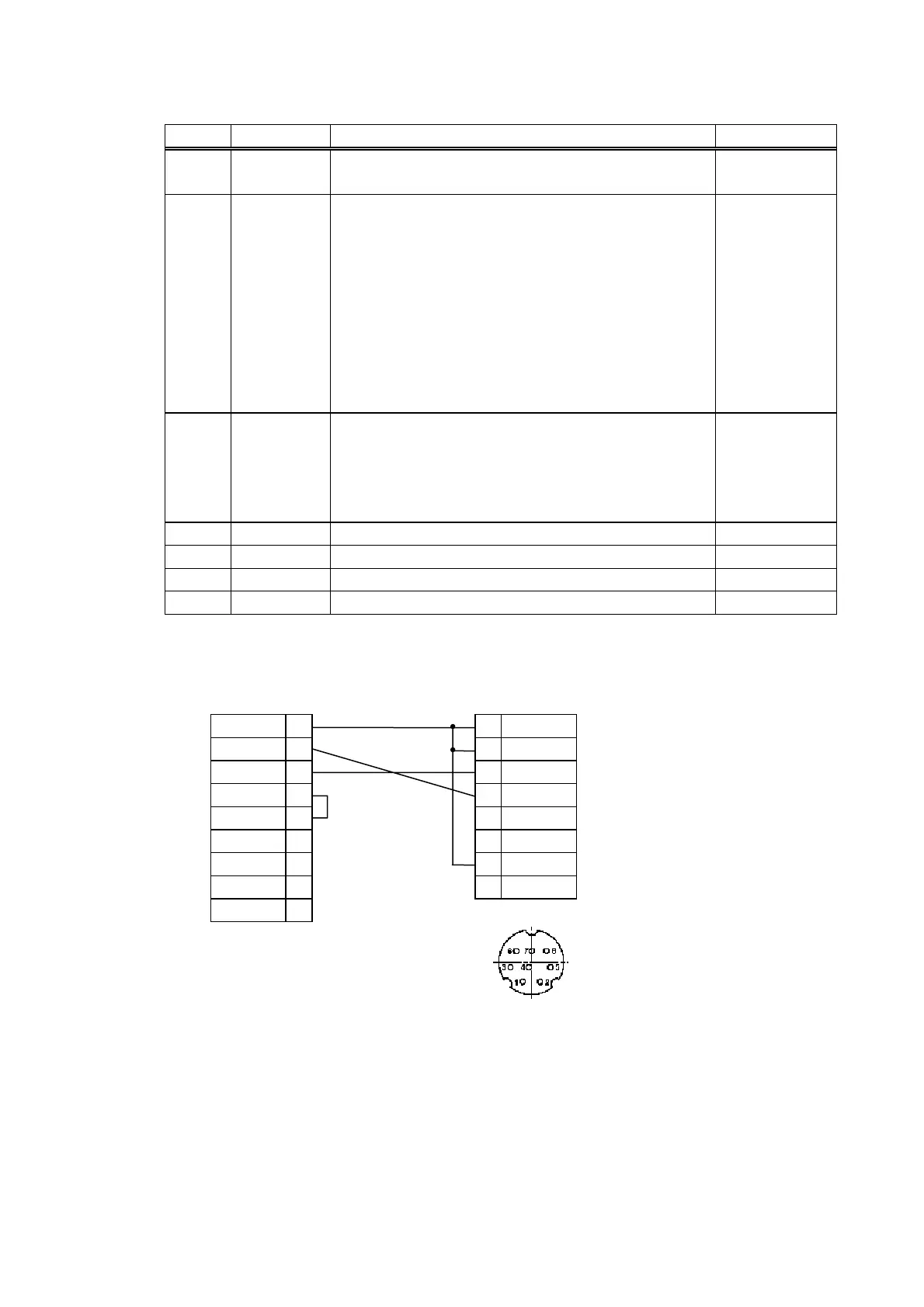
(2) Wire connection diagram
[Host] [Printer]
GND 5 1 SG
RXD 2 2 SG
TXD 3 3 RXD
CTS 8 4 TXD
RTS 7 5 CTS
DCD 1 6 RTS
DTR 4 7 TEST
DSR 6 8 N.C
RI 9
 Loading...