9 2D system measurements
For this sensor ... This pin ... Is below this pin ...
Boom (with VAboom) B1 A
VAboom B B1
Stick B G
Bucket F D
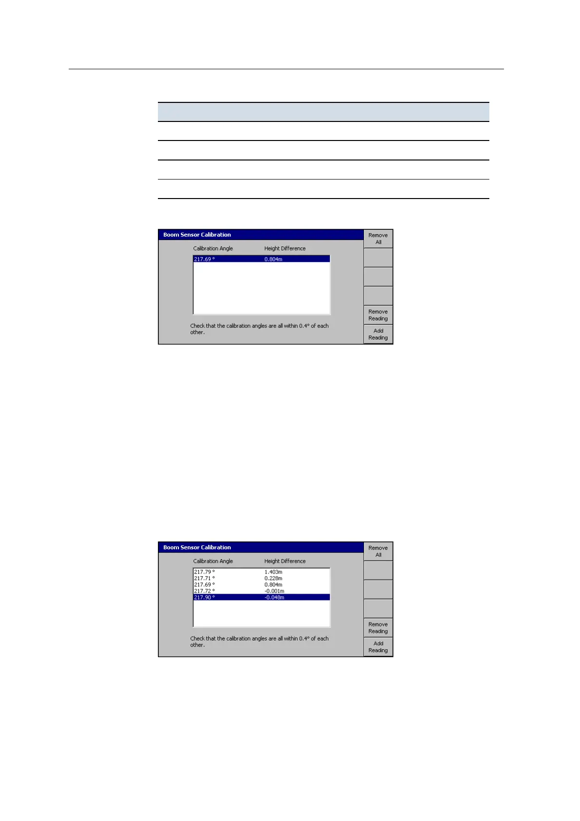
6. Press Calibrate. The software calculates the calibration angle:
The above dialog shows an example where the stick pin is above the boom pin
by 0.804meters and the calculated calibration angle is 217.69°.
7. To add another calibration reading to the list, press Add Reading.
Note – For system operation you only need one reading. However, the more
readings you take, the greater the reliability of the calibration.
8. Move the boom, stick or bucket to a different position and repeat Step2 to
Step5.
Tip – Calibrate each sensor through as wide a range of angles and height differences
as possible. This results in a more accurate overall calibration.
Every time you perform a calibration, the system records the calculated
calibration angle and height difference.
The following dialog shows the boom sensor calibration list:
118 GCS900 GradeControl System for Excavators Installation Manual