Installing Fixed Sensor Components 8
5. Torque the bolts to 210 N-m ± 20 N-m (155 Ft-Lbs ± 15 Ft-Lbs).
6. Position the locator plate (6) so that:
the screw holes in the bracket intended to receive the allen head screws
(7) provided are visible through the slot in the plate
the locator plate snugly engages the bottom plate of the sensor. A properly
fitted locator plate lets you remove and re-install the sensor in its initial
position.
7. Secure the locator plate to the sensor bracket using the allen head screws.
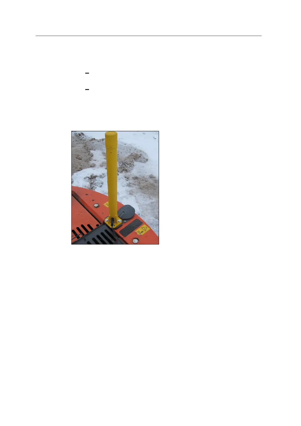
The following image shows the mounted cab rotation sensor.
8.5 Connect fixed sensors
The GCS900 Grade Control System supports a wide variety of fixed sensor and
mast combinations. It is beyond the scope of this manual to document all possible
combinations. The following combinations are documented:
l Body, boom and stick angle sensors
l Bucket angle sensor
l Tilt bucket angle sensor
l Cab rotation sensor
GCS900 Grade Control System for Excavators Installation Manual 81