2D system measurements 9
1. For a tilt bucket, ensure that no tilt is applied, and that the bucket is square to
the tracks of the machine.
2. Extend the bucket ram to approximately halfway.
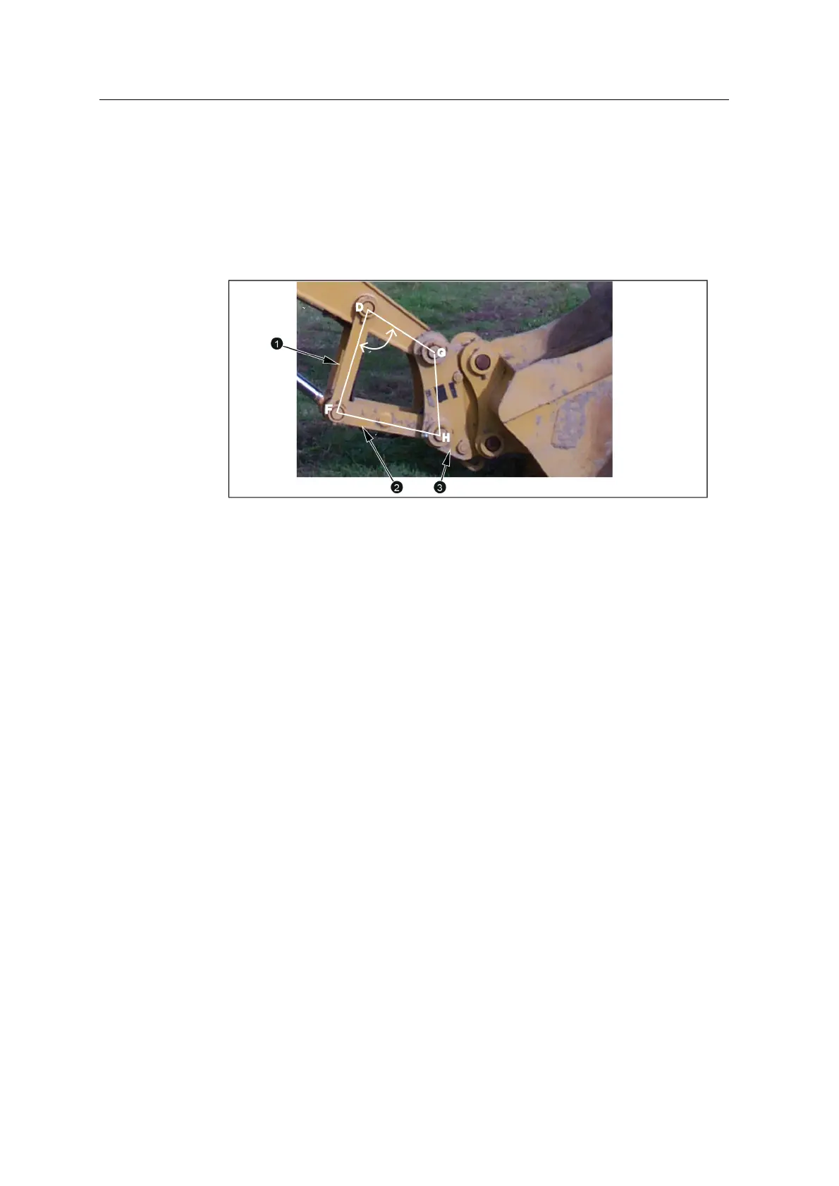
3. For Cat PSC systems, or when the bucket sensor is mounted on the idler arm/
dogbone, put the linkage points D, G, H, and F into an approximate rectangular
shape, with the internal angle at point D close to 90°:
1
IdlerArm/Dogbone
2
Power Link
3
Quick Coupler
Unless otherwise specified, do not move the machine body or arm while you
take the measurements.
9.9.1 G–H / G–J
Measure from the:
l bucket pin G to linkage pin H.
Note – This measurement is required only when the bucket sensor is mounted
on the idler arm/ dogbone, or with a Cat PSC system.
l bucket pin G to bucket teeth J. Because the bucket may not be symmetrical,
measure from both sides of the pin and use the averaged value.
GCS900 Grade Control System for Excavators Installation Manual 97