3D System Measurements 10
measurement is critical to system accuracy, do not take it for granted that the
default value is correct.
It is important to check that the sharp, pointed screw-in foot on the range pole is
tightly screwed in and not clogged with dirt.
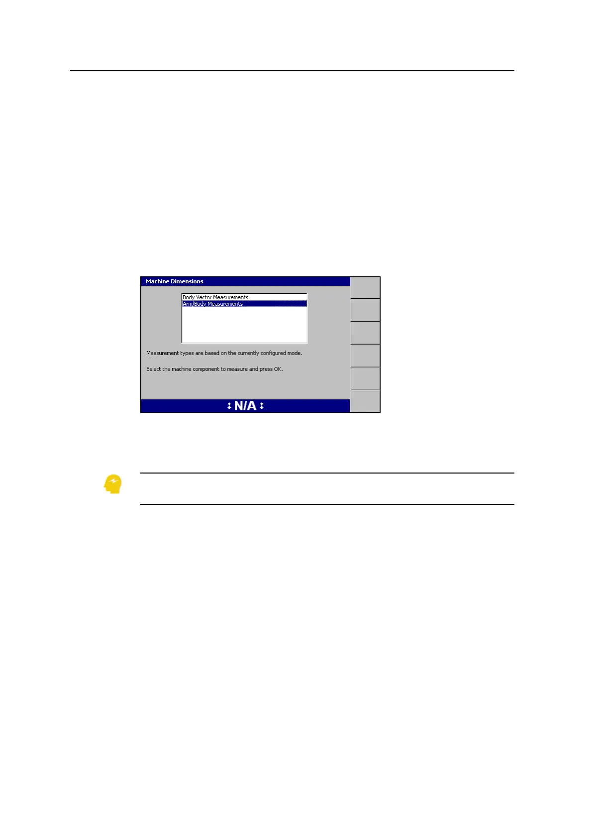
10.4 Machine dimensions
Use the Machine Dimensions wizards to enter your machine measurements into the
system.
To access the dialog, from Setup Menu – Installation, select Machine Dimensions:
The measurement types that appear depend on the type of system that you are
currently using (3D or Depth and Slope).The Body Vector Measurements option
does not appear for Depth and Slope systems.
ATTENTION — Valid machine measurements are critical to system operation. Make sure that
you enter all of the required measurements for your system type.
10.4.1 Boom range pole target to boom centerline
Note – This measurement only applies to GNSS and UTS systems.
1. Mark the centerline of the boom, in line with the center of the bucket, between
the boom pins:
GCS900 Grade Control System for Excavators Installation Manual 129