9 2D system measurements
9.10.3 Boom pin - lateral and reach offset
Note – For machines with displays that support 3D excavator guidance, this
measurement can be done automatically, by selecting "Yes" in the field "Use
automatically calculated Boom pin offsets" in the Machine Body dialog. See 9.11.1
Arm/Body Measurements.
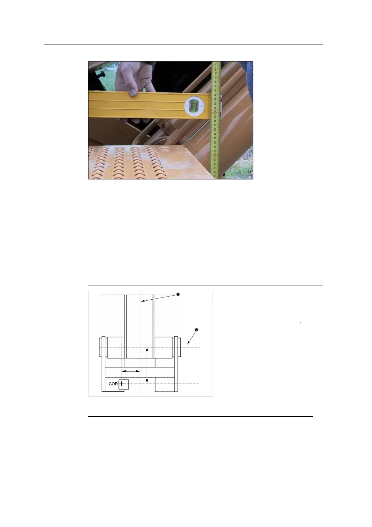
To perform the measurements manually, measure from the:
l Center of rotation (COR) to the boom centerline
l COR to the boom pin centerline
1
Boom centerline
2
Boom pin centerline
The above image shows positive measurements, measured looking forward; the
measurements are negative if the:
102 GCS900 GradeControl System for Excavators Installation Manual