9 2D system measurements
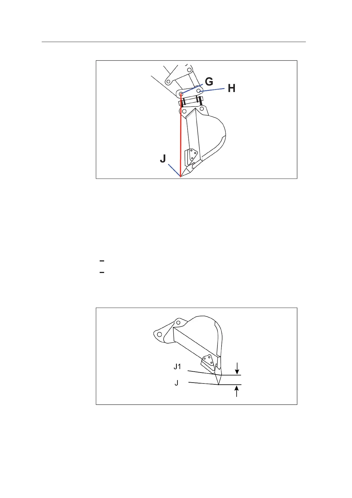
Note – For the bucket sensor calibration the bucket points G-J need to be
vertical.
9.9.2 Bucket wear J–J1
Note – This measurement is required when you create a new bucket, or modify an
existing bucket.
1. For a new bucket, define the bucket wear control point (J1):
identify a point near the bucket tip, that you can easily measure to
mark the wear control point on the bucket. This is the reference point (J1)
for measuring the bucket wear.
2. Measure from the bucket cutting edge point J to the bucket wear control point
J1.
98 GCS900 Grade Control System for Excavators Installation Manual