10 3D System Measurements
10.1 Introduction
For systems that use one or two GPSreceivers or a UTS for 3D guidance, you must
accurately establish the location of the 3D sensors relative to the boom pin and
bucket prior to beginning work with the machine.
10.2 GPS receiver over bucket / boom pin
Use these techniques, when you take the GPS body vector measurements.
If you use a UTS to take the body vector measurements, use the same technique to
set the UTS up over the bucket/boom pin.
For more information, see 10.4 Machine dimensions.
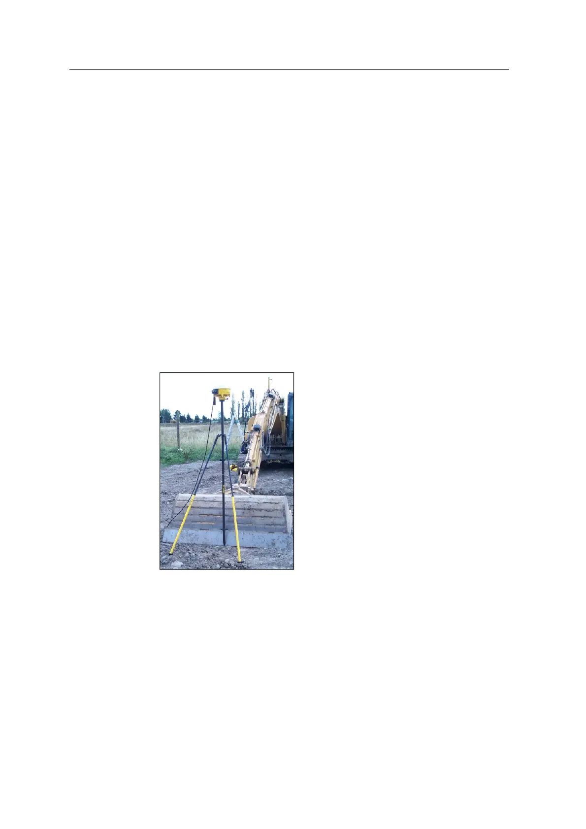
10.2.1 GPS receiver over bucket
1. Use a bipod, range pole and pole adaptor to set up the right GPS receiver over
the center of the bucket. You need to set up the machine at maximum reach:
2. Connect the GPS measure-up cable between the receiver and any 6–pin female
sensor connector on the harness.
3. Adjust the bipod legs until the level on the range pole shows that the pole is
vertical.
126 GCS900 GradeControl System for Excavators Installation Manual