9 2D system measurements
ATTENTION — Valid machine measurements are critical to system operation. Make sure that
you enter all of the required measurements for your system type.
9.11.1 Arm/Body Measurements
From Machine Dimensions, select Arm/Body Measurements.
The pages that appear in the Arm/Body Measurements wizards vary according to
the type of system you have:
l bucket sensor mounted on bucket/quick coupler
l bucket sensor mounted on idler arm/dogbone
l Cat PSC System
See also 9.3 Measure up worksheets.
Bucket sensor mounted on the Bucket/Quick Coupler configuration
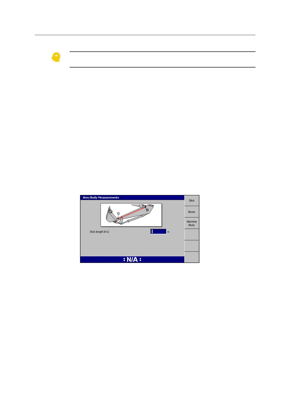
1. The first page of the Arm Body Measurements dialog is for the stick
measurements. When the bucket sensor is mounted on the bucket or quick
coupler, the system requires only the stick length B-G to be measured:
Note – The system automatically calibrates the bucket sensor at the time the
bucket is created, removing the need for Bucket Sensor Calibration in the
'Calibrate Sensor' dialog.
2. Enter your stick measurements into the dialog.
3. Enter the machine measurements for each softkey.
Note – The VA Boom and Laser Catcher softkeys only appear when you have
configured your system for a VA boom and/or laser catcher.
Note – For machines with a VA boom, the ‘Boom measurements’ page changes
to reflect the required measurements.
4.
Press \.
106 GCS900 GradeControl System for Excavators Installation Manual